- Introduction
- Modularize design
- Choose accelerometer
- Design
- Layout
- Next step
Introduction
In our research group short term plan, we plan to mount some sensors including SAR Radar on the UAV for some special missions, so we need a fairly stable UAV platform. We can simple buy vibration absorbers and assemble a lightweight stable frame, but we dont know the vibration characteristics on frequency domain, and especially for Radar application, it is crucial to measure the vibration amplitude, frequency, power, even phase for signal compensation.
In case that out lab has limited budget and those commercial grade vibration meters are very expensive, I decided to build myself.
Criteria
- High bandwidth (As high as possible, because motors on the drone are working at high rpm)
- Lightweight. Heavy measure unit will change the platform characteristic.
- Easy digital interface. This tester may be left on the drone as permeate sensor, so it should have good digital interface for companion computer.
- EMI proof. UAV is known as having noisy electromagnetic environment, though we have not measure the EMI at this moment, I need to take consider of it.
Modularize design/UNILINK
Also, in order to speed up my PCB design iteration, I start to modularize my design and designed an architecture to standardized powering and low-level interfacing which I gave the name UNILINK.
Modularize design
It is not a new topic, but at the time that I can foresee a lot of digital system to design in our UAV, I can put most using sub-system on its own board, rather than just keeping schematic and re-layout every time. For example, I have designed three power modules:
- wide range 12V output module: Using switching regulator that accepts 12V to 40V voltage input, and provides 12V output.
- wide range 5V output with CAN: Similar with “wide range 12V output module”, but this module also have CAN bus over power line, that we can broadcast low-level and essential messages to the bus. (Heartbeats, temperature, emergency trigger)
- 3.3V LDO output
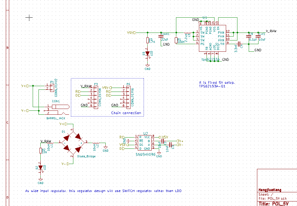
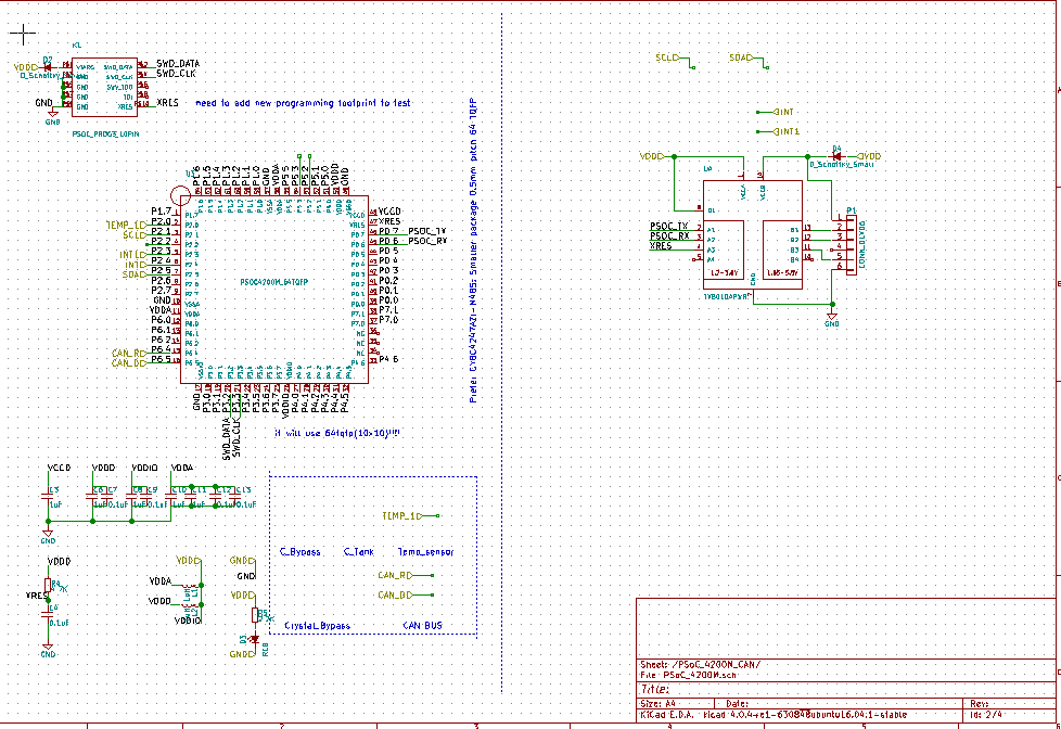
schematic of wide range 5V with power_over_can
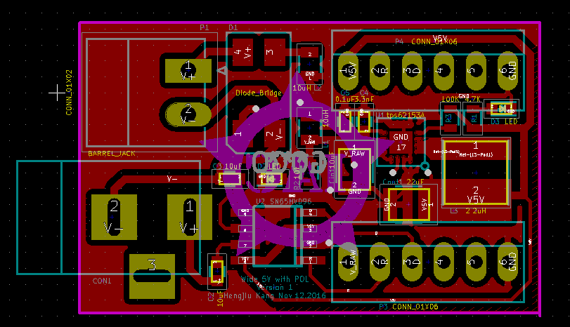
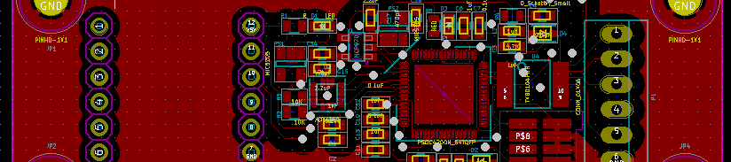
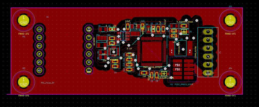
layout of wide range 5V with power_over_can(Bottom layer hidden)
UNILINK
At the time when I think about modularized module, I also plan to split the system communication interface to ISO-like style. From the bottom layer to higher layout, I will implement different interface, making sure that different modules can talk to each other and the system has clear design outline.
For example, CAN bus will provide essential status information including heartbeats, module ID, emergency triggering signal, force on/off signal. Higher than that, because I will put a PSoC MCU on each sub-system, all the module will sit on some high speed serial port bus that is fast enough to transmit messages in XBEE’s API syntax or wrapped by rosserial package grammar. Xbee and bluetooth will be available at this layer. For even higher speed connection, Ethernet will be used. Very possible in the near future that when I have done the TCP/IP compatible CAN bus on Ethernet(Profinet, Modbus TCP, EtherCAT, etc), all the connections can be transmit via high speed link.
Known issue: PSoC 3/5LP do not have TCP/IP implementation, creating such module from scratch from UDB and FPGA is tons of work, and porting library from other micro-controllers as mentioned in this thread is possible, but potentially will cost a lot of CPU time.
So right now, I only implement the baseline CAN-over-power interface in the power module design.
Choose accelerometer
There is always trade off when picking up IC/sensor. In this design, the trade off consists of price, bandwidth, precision and axis.
| Name | BW | Comm | Axis | Noise | g-range | Price |
|---|---|---|---|---|---|---|
| ADXL001 | 22K | Analog | x | 4mg/rtHZ | 250g, 500g, 700g | $13.29 |
| ADXL350 | 1.6K | digital | x, y, z | 1 LSB | 1g, 2g, 4g, 8g | $4.57 |
ADXL001 analog accelerometer has incredible high bandwidth to 22KHz, but the downside is that it has relatively low precision and it only have one x-axis. Also, this analog accelerometer has very high g-range(lowest to 250g), which means is has low resolution, comparing to the ADXL350. In order to simplify the first version design and confirming the feasibility, I picked ADXL350.
Design (Will be updated shortly)
Top design
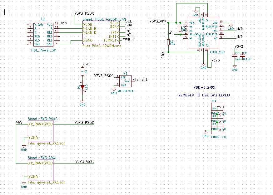
This design is as simple as having three parts:
- Power unit
- PSoC4200M series micro controller
- ADXL350 3-axis sensor
PSoC 4200M Design
I used CY8C4247AZI-M485, because it is the only MCU equipped with CAN module in the PSoC 4200M series. Other than PSoC5LP, PSoC4200M does not have multiple GPIO rails, so all the gpios on the PSoC4200M are working in the same voltage level. The benefit is obvious: less decoupling capacitors.
This design schematic was copied and pasted from my standard design library, so those add-on design, including bypass capacitors, tan capacitors and external crystals are all left blank.
One noticeable trick is adding a level shifter on the UART connector, then this board is ready to communicate with both 3.3V and 5V FTDI cable without problem.
Of course I admit that using a PSoC4200M is pretty overkill, but I have to say, since I am in developing and process, it is far more important to standardize the design process and speed up the developing progress. Smaller and cheaper is always good, but I concern more about the time cost.
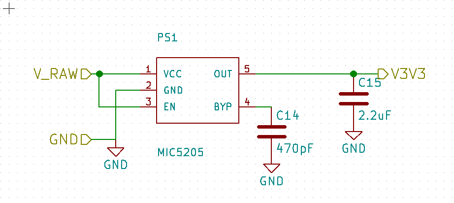
3v3 LDO Design
Layout
According to the ADXL350-datasheet, ADXL350 chip should be put at the center of PCB with four mount screws on each corner in order to minimize the self-vibration.
Last update: Nov.22 2016
Last update: Nov.20 2016
Last update: Nov.19 2016