New blog update method: Start from this post, I will use this blog as lab record, and update the post along with my project.
Post overview
- Background
- Brief of SLAM
- Plan
- Milestone 1: Lidar SLAM on Turtlebot simulator
- Milestone 2: Lidar SLAM on the back
Background
I am still in the UAV project, and we are in the new stage: Implementing Autopilot. After final stage of Intel-Cornell cup, I kept thinking about future of UAV. UAV is useful, having lot of potential, true. But UAV at this moment UAV is somehow not useful, also true. Concretely, UAV is not clever enough to do many missions. Autopilot is not defined by “Auto” “pilot”, but more broaden idea – consciousness. Collision avoidance, target following, even much more complex tasks, can be done after the UAV having consciousness of what happened. The prologue of this consciousness is SLAM.
Brief of SLAM
SLAM refers to “Simultaneous localization and mapping”, early started many years ago, and recently been boosted by rapidly improved computer power.
The basic idea of SLAM is collecting geometry information from environment, plotting point cloud in the computer, and estimate current position (relative). It is independent navigation method that requires no external devices like GPS, UWB, Beacons.
Google tango is a famous example:
Nevertheless the SLAM is intended for navigation, after Neural Network and Machine Learning had become the next hot topic, SLAM will be the best friend of Autopilot/Auto-driver, because it provides rich information for environment reconstruction. SLAM is eye for the machine brain.
Plan
Lucky, SLAM and Autopilot can be developed individually – they are not parasites to each other. Let me focus on SLAM side first. For faster developing and easier debugging purpose, I will deploy SLAM on my ground vehicle first.
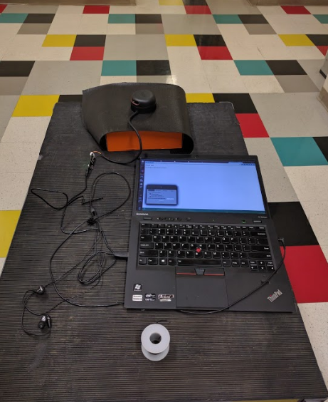
Before I finish the hardware design (RC router, control interface, etc), a easier way to implement SLAM in practical is the title – SLAM on the back. Concretely, I will stick an IMU on my Lidar and keep them in right hand, use my another hand carry the laptop, walking inside the building, making sure that everything is understood(Im sure I can).
I found that iterative developing or “agile developing” is useful, though it may take more steps and more time, but usually when I am working on hardware design, it is more likely that I stuck at some point, so I will move small step forward one by one.
Milestone 1: Lidar SLAM on turtlebot simulator
Turtlebot simulator is already there, with the least risk bringing the most progress. After some research and study, here is what we need, or the road map:
Pause. Here is the problem. Turtlebot SLAM simulation have not been updated since ROS indigo, and ROS indigo is not compatible with Ubuntu 16.04. So our setup will be:
Ubuntu14.04+ROS indigo+Gazebo4+Turtlebot SLAM demo
There is no trivial. Every step follows the tutorial.
Milestone 2: Lidar SLAM on the back
Adding the least amount of hardware, Lidar and IMU, to the system can minimize the uncertainty. At this step I will feed Lidar output and IMU output to the system, looking for plotting and locating myself in the building.
I will create such demo based on ROS gmapping package, and according to the gmapping tutorial page, we can use the following command to start gmapping_slam script.
rosrun gmapping slam_gmapping scan:=base_scan
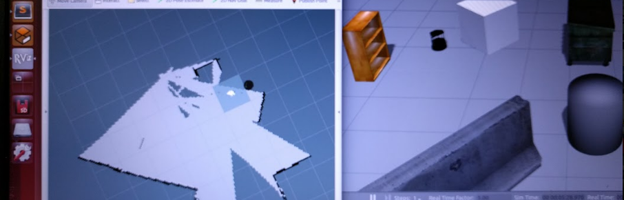
Then I execute rviz to visualize the data:
rosrun rviz rviz
After having rviz executed, I added map to the monitor list
![]()
Topics that we need for gmapping_slam
Nothing appeared, but I am already satisfied by no error pupped up. No information feed in , no mapping generated out. So let me read ROS Gmapping documents to see what it requires. gmapping document page I found that it only subscribe two topics:
Subscribed Topics

tf (tf/tfMessage)
	Transforms necessary to relate frames for laser, base, and odometer (see below)
scan (sensor_msgs/LaserScan)
	Laser scans to create the map from
Then check topic definition of tf and scan:
topic: tf
Header header
    uint32 seq
    time stamp
    string frame_id
string child_frame_id
Transform transform
    geometry_msgs/Vector3 translation
        float64 x
        float64 y
        float64 z
    geometry_msgs/Quaternion rotation
        float64 x
        float64 y
        float64 z
        float64 w
topic sensor_msgs/LaserScan
# Single scan from a planar laser range-finder
#
# If you have another ranging device with different behavior (e.g. a sonar
# array), please find or create a different message, since applications
# will make fairly laser-specific assumptions about this data

Header header            # timestamp in the header is the acquisition time of
                         # the first ray in the scan.
                         #
                         # in frame frame_id, angles are measured around
                         # the positive Z axis (counterclockwise, if Z is up)
                         # with zero angle being forward along the x axis

float32 angle_min        # start angle of the scan [rad]
float32 angle_max        # end angle of the scan [rad]
float32 angle_increment  # angular distance between measurements [rad]

float32 time_increment   # time between measurements [seconds] - if your scanner
                         # is moving, this will be used in interpolating position
                         # of 3d points
float32 scan_time        # time between scans [seconds]

float32 range_min        # minimum range value [m]
float32 range_max        # maximum range value [m]

float32[] ranges         # range data [m] (Note: values < range_min or > range_max should be discarded)
float32[] intensities    # intensity data [device-specific units].  If your
                         # device does not provide intensities, please leave
                         # the array empty.
The Lidar I used, RPLidar V2, provides nice API/SDK, so I can just us its API to publish scan information. Actually, API/SDK provides a demo software:
NOTICE if rplidar sdk/api reminds “cannot bind usb port” error, that is because your current user does not have permission to use ttyUSBx port. Usually you can use sudo, but since ROS is installed for user, you can execute the following command to add user to dialout usergroup:
sudo adduser $USER dialout
The problem is tf topic. In case that we will mount Lidar on the back (or in hand), how do we know my current position? I do have several 9-axis sensors, so I need to estimate my position by using some technology.
BTW, I strongly recommend BNO055, 9-axis motion sensor from Bosch, which has a cortex-M0 inside, and just output filtered and converted data ready to use.
By some googling, I can use robot_localization package from ROS. It seems like this package is not straight forward, but I will look into it. Nevertheless, I can write my own estimator.
Prepare location estimator
ROSCON 2015
Robot_localization introduction ppt
This is quick start video about robot_localization on ROSCON conference. It provides important feature and configuration samples. Though I am still not sure about different frames (base_link, odom, map), I can feed necessary data into base_link frame to see if this node can give me estimated location/position.
REP 103 & REP 105
REP referes to Ros Enhancement Proposal, it contains group of suggestions and conventions that making different developers have “the same tone”.
REP 103 proposes Standard Units of Measure and Coordinate Conventions
REP 105 proposes Coordinate Frames for Mobile Platforms
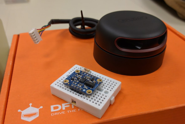
Hardware I have
Here is what I have: RPLidar V2 and BNO 055 with arduino UNO that I always carry with me.
Install robot_localization
cd ~/catkin/src
git clone https://github.com/cra-ros-pkg/robot_localization
cd ..
catkin_make
source devel/setup.bash
Install rosserial
rosserial is not necessary, but in order to save time (its already 21:45 and I plan to get this project done by the end of today), I turn to use rosserial package to directly publish the tf topic to the laptop.
This package has two part: Arduino side “client” part and computer side interpreter.
- download git repo from https://github.com/ros-drivers/rosserial.git to catkin_ws/src
- catkin_make
- Following the rosserial_arduino to generate arduion library.
- Then I can see the “ros_lib” from my Arduino IDE.
- Load sample program odom to the arduino, then start server side by
rosrun rosserial_server serial_nodeHowever, system constanly gives me this error:
[ INFO] [1479449266.767625912]: rosserial_server session configured for /dev/ttyACM0 at 57600bps.
[ INFO] [1479449266.768006176]: Opened /dev/ttyACM0
[ WARN] [1479449266.768145627]: Socket asio error, closing socket: asio.misc:2
Oh…It’s my bad. According to the beginning tutorial, I should use the following command:
rosrun rosserial_python serial_node.py /dev/ttyACM0
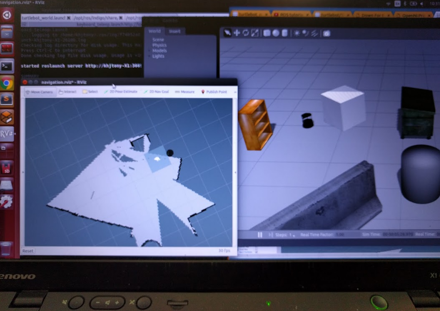
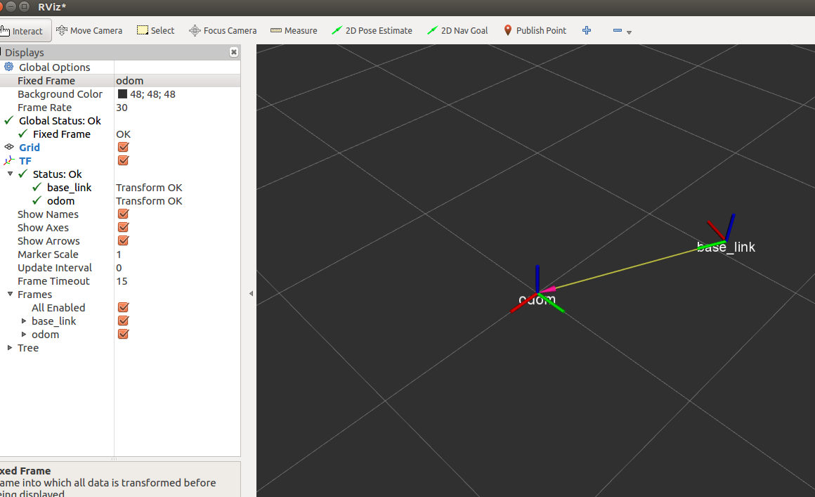
Now I can see an object flying around center point in rviz:
Last update: Nov.18 2016, well, I did not finish it on time.
Odometry data for gmapping
ros_gmapping package require odometry data. In my setup, I dont have encoder or GPA (In door), so here are two solutions:
- Using hector_mapping instead of gmapping
- Check if ros_localization package is able to give odometry data.
- Using some intermediate package to mocking odometer by IMU and laser.
Frame
Before I go further, I found a critical idea that I am not quite familiar with Frame
Concretely, TF defines relative geometry relationships between each object in the robot system. For example, let me cite this photo:
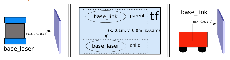
By the way, I strongly recommend to go through the whole tf tutorial. It is essential.
*Last update: Nov.19 2016
Install hector_map
After some research, I will go through the hector_map+Laser solution.
Install hector from hector_slam is easy, but it requires Qt4.x, and Qt5.x is not compatible with current version of hector_slam.
Ubuntu users can do the following:
sudo apt-get install qt4-default
sudo apt-get install qt4-dev-tools
Then go to the catkin folder to
catkin_make
Create our slam_on_back package
In catkin/src, create my slam_on_back package by typing:
catkin_create_pkg slam_on_back roscpp rospy hector_mapping rplidar tf robot_localization
I always have the following error:
No transform between frames /map and /base_link available after xxxx seconds
Lucky, I found this blog (in Chinese),
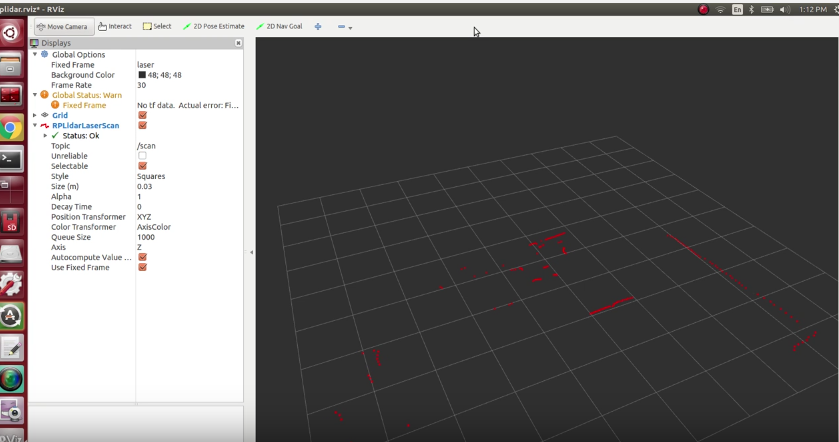
SLAM with RPLidar
which reminds me that rplidar_ros.git has slam branch.
It seems like this branch has been deprecated, but configuration file/launch file can be used.
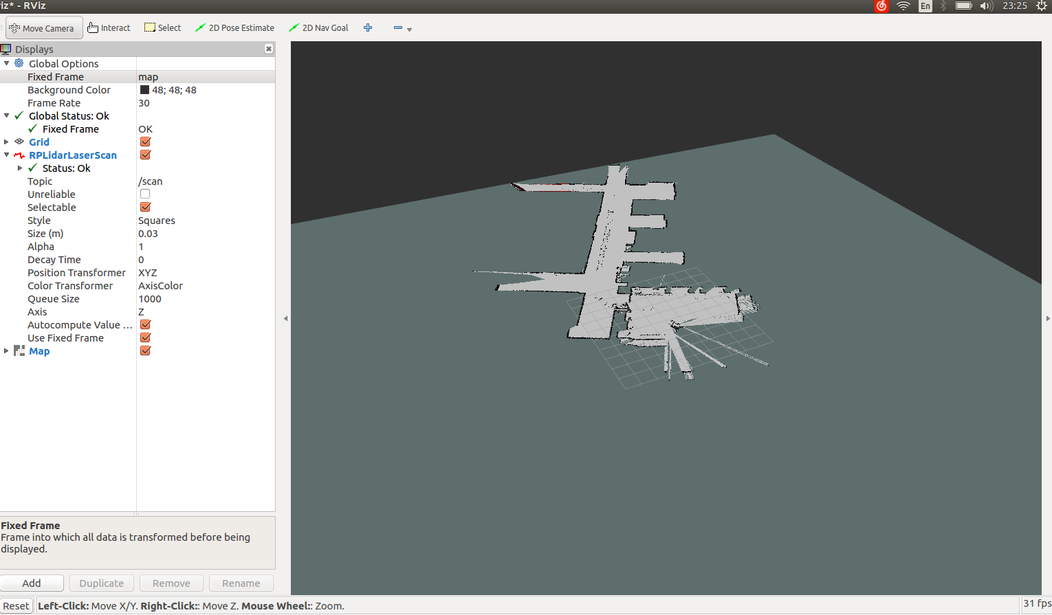
Finally I got this work.
Things is simpler than I thought. Theoretically I need to put design/setup with gmapping, because hector map does not depends on odometer and RPLidar v2 has bad update rate (~10Hz) and short sensing range (~6m), but I want to save time and directly move to the next step. Source code can be checked in the github
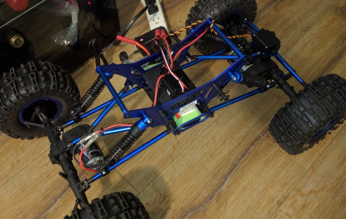
Next step: SLAM on the vehicle
I have two vehicle platforms as following:
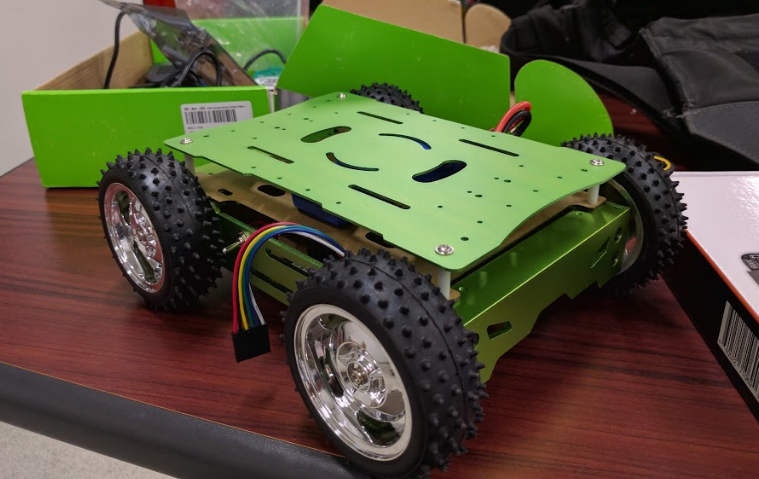
So the next step will be mounting this SLAM setup on the vehicle, with odometer data available (Via IMU or other sensors)
Project setup and source code
github: slam_on_back
Package directory:
./
├── CMakeLists.txt
├── include
│   └── slam_on_back
├── launch
│   ├── hector_test.launch
│   ├── rplidar.launch
│   ├── rplidar_mapping.launch
│   ├── rplidar_mapping.launch.old
│   ├── test_rplidar.launch
│   └── view_rplidar.launch
├── package.xml
├── README.md
├── rviz
│   └── rplidar.rviz
└── src
I will explain each file when I have time.
Last update: Nov.19 2016
Last update: Nov.18 2016
Last update: Nov.17 2016
Last update: Nov.16 2016