Post overview
- Background
- First try
- Analysis
- Second try and result
Background
In my SAR Radar back-end design, I need my PSoC 5LP to sample TX and RX simultaneously. Radar also provides an “enable” signal indicating that radar starts a new sampling cycle. Our radar is FMCW radar, so making sure that TX/RX samplings are in phase is very important. Here is my top design in the PSoC Creator:
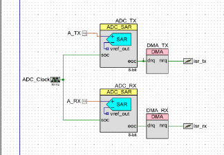
ADCs are driven by internal clocks at ~1MHz. ADC sampling is driven by ADC_Clock signal at ~44.1KHz, so ADCs’ samplings will be in phase. But how about sampling delay between each radar sampling cycle?
!QUESTION: Are those two samplings in phase with radar’s cycle?
First try
One of the most straight forward though would be add an interrupt on enable signal from radar that when enable signal is high, start the sampling trigger clock. However, we know that software solution always have latency. So another hardware side solution would be add an “AND” logic between enable signal and sampling trigger signal.
Ins’t it easy?
Experiment on PSoC
[Need to add correct screenshot]
In the first try, I set up two methods: software interrupt and hardware synthesized “AND” logic.
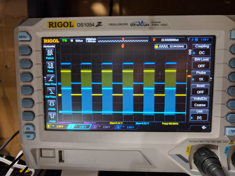
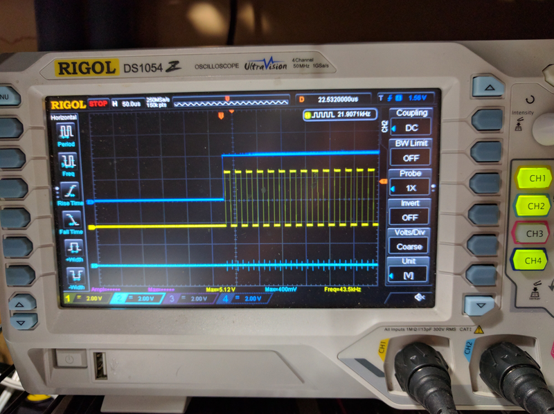
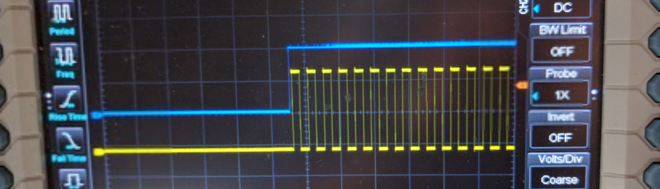
At large scale, both clock signals seem good. Upper blue signal is mocking radar enable signal from function generator. Yellow signal came from software interrupt and lower blue signal came from “AND” logic. Let’s zoom in.


Apparently, yellow signals are not in phase. Another clock has the same issue.
Analysis
The problem is that external enabling signal is not synchronized with ADC_Clock signal. Clock module in PSoC does not have enable or reset pin, but PWM module has. Using PWM module instead bare clock module provides possibility to hold output until external enable signal.
Second try and result
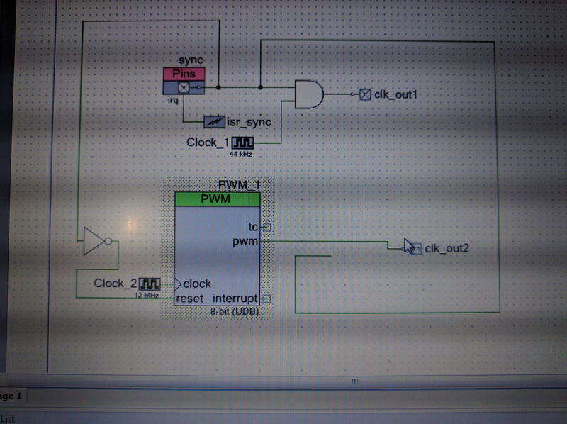 So my top design uses PWM as clock generator, and use external enable signal to reset the PWM module. When enable signal is LOW, PWM module is halt , and when enable signal goes HIGH, PWM module start to work. Actually we cannot eliminate delay completely, but we can make is shorten by driving PWM module with 12MHz high frequency clock input. On the other words, PWM output is synchronized with enable signal at 12MHz sampling rate.
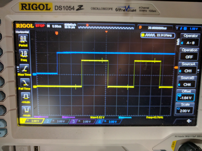
Checking oscilloscope, we got ideal result:
So my top design uses PWM as clock generator, and use external enable signal to reset the PWM module. When enable signal is LOW, PWM module is halt , and when enable signal goes HIGH, PWM module start to work. Actually we cannot eliminate delay completely, but we can make is shorten by driving PWM module with 12MHz high frequency clock input. On the other words, PWM output is synchronized with enable signal at 12MHz sampling rate.
Checking oscilloscope, we got ideal result: