- Introduction
- Overall design
- Get hands on!
- Placement in the car
Introduction
After the computer racks been installed, power became a serious problem. The battery in my car obviously cannot afford the onboard system running for more than couple of hours. This can be veryfied by simple calculation:
energy = time * power (1)
In this formula, let us define energy as half of my car battery which is around:
0.5 * 30Ah * 12V = 180Wh (2)
Currently we have a laptop, a POE switch and a LTE router always be on, which drain continuous 30w power. Brining this power assumption back to formula (1), we get:
time = 180Wh / 30W = 6 hours (3)
6 hours is even less a whole night. So I need to carry more batteries in my car in order to support at least 2 days operation time.
As a solution, the PowerBox 2 came up. This is an updated version of PowerBox which I have tested for a while. PowerBox is made by a single 12V battery which does not have enough capacity, so in the PowerBox 2 design, I put three batteries in the system, and then build a new power distribution box to control the charging and discharging features. The power distribution box has enough room for future upgrade.
Overall Design
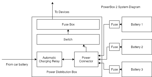
The PowerBox 2 system has two major parts:
- Power Distribution Box
- Plug in Batteries.
The power distribution box is used to accept charging power from car battery, and it has electricity connections to external batteries. It also has a large fuse box to power on devices.
External batteries are normal vehicle lead batteries.
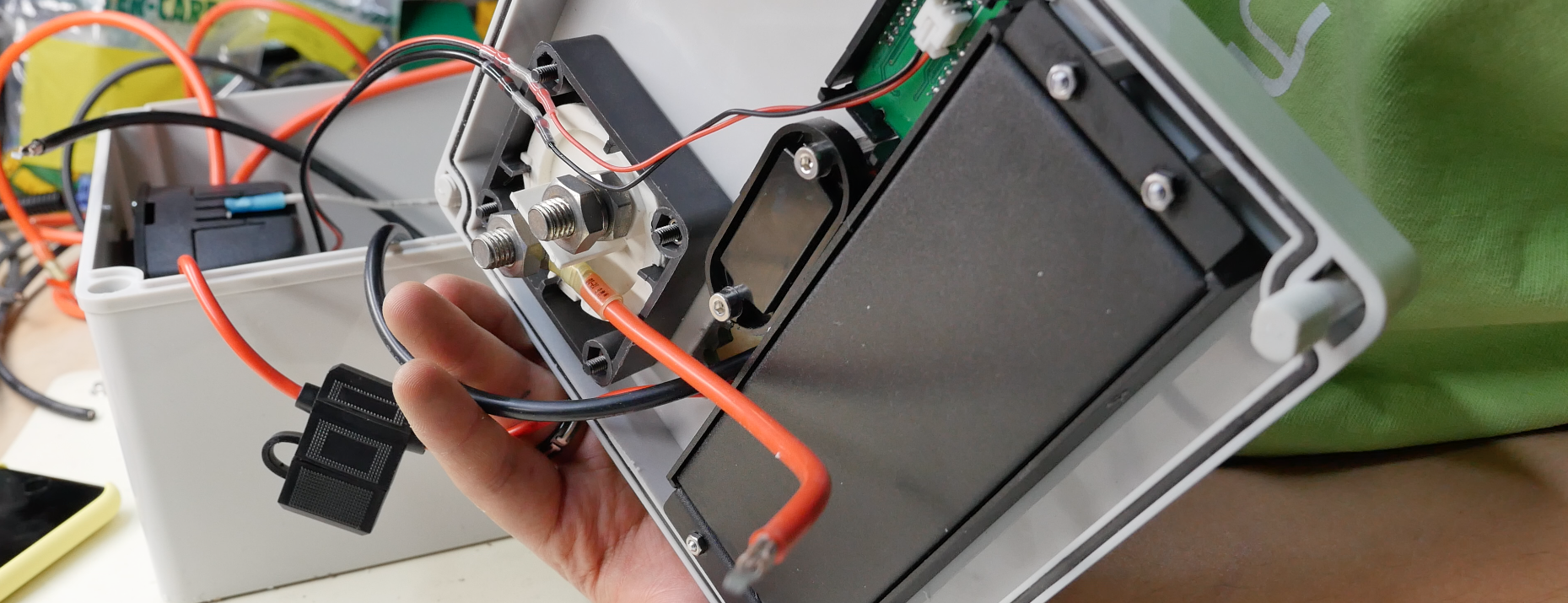
Automatic Charging Relay

Directly connecting car battery to external batteries is risky even with fuse sitting in between, because batteries will be dead if onboard devices are running for extended time. This relay will contact only when vehicle engine is ignited, thus provides isolation between the vehicle battery and external batteries.
Connecting multiple batteries
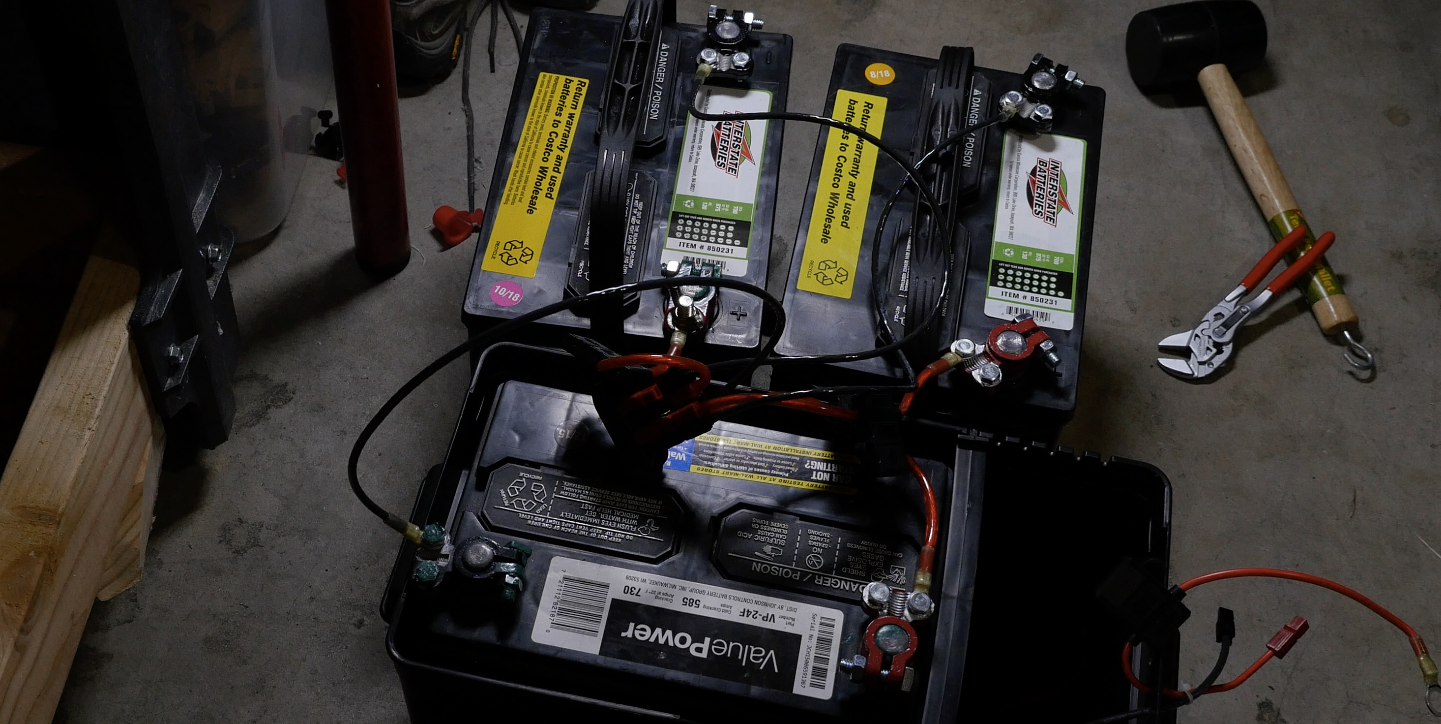
I think that it is not safe to directly connect multiple vehicle batteries together, because batteries have different charging conditions and simply connecting them together may result in very high current thus either damage the 10AWG cable – the thickest cable I have in the garage. So I charged them individually to a similar voltage level and then use short cable to connect them together for hours.
Output stage
In my design, this PowerBox should have two output stages: Always-ON and Controllable. And the PowerBox should also report voltage, current and other messages over some bus, maybe CAN bus.
However at this moment, I have not decided how to accomplish this design, because this topic involves many other design concerns. For example I need to pick up a MCU that is cheap, and easy to program. The MCU should have rich hardware resources to support CAN(CANOpen) protocol, and the MCU should cheap enough because once I decide to use CAN bus, all the low level modules can only use the MCU with CAN bus support. However a full-featured MCU with CAN bus support is never cheap, and CAN bus is limited in message format. If I want to have a more versatile field bus that can transmit high capacity data in stream for example the remote terminal or HMI, RS485 maybe a better choice. However high speed duplex RS485 requires 4 data lines, brings up more problems in PCB designing and layout.
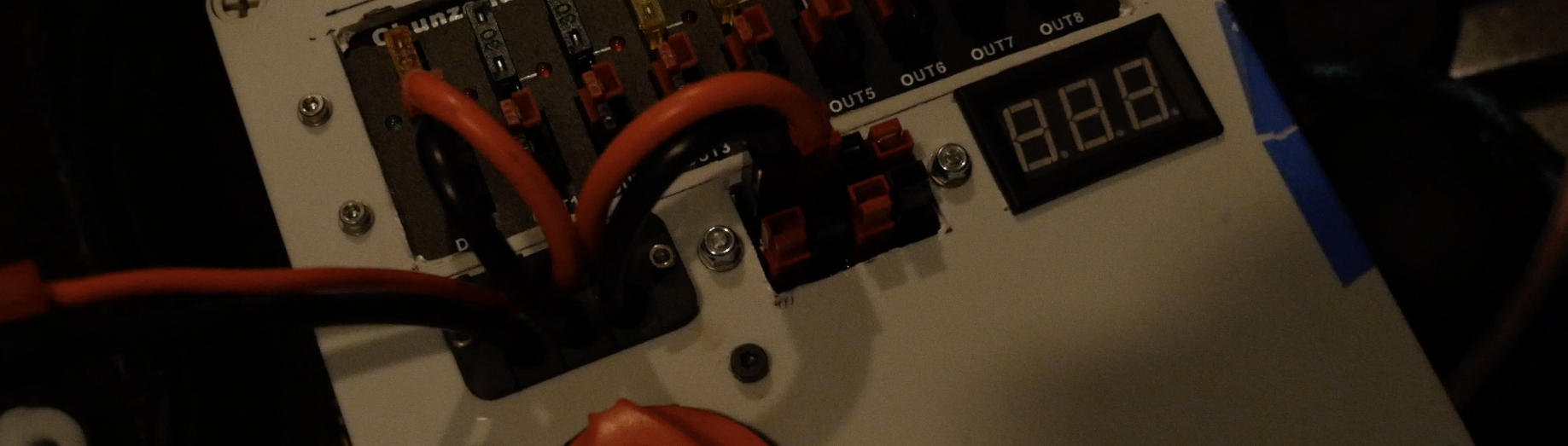
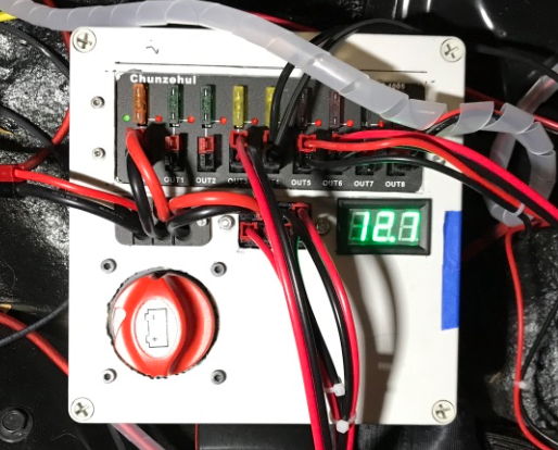
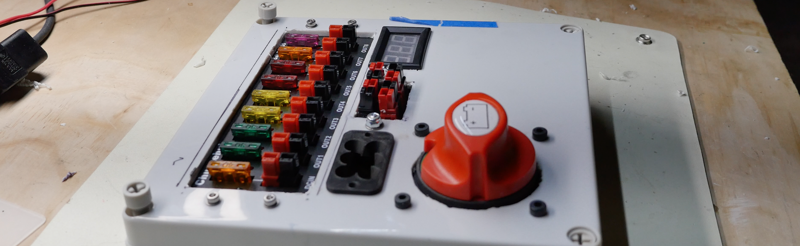
As a result, I only put a fuse box as Always-ON output stage on the PowerBox and leave enough room in the box for future upgrade.
Get Hands on!
Prepare the individual Battery box
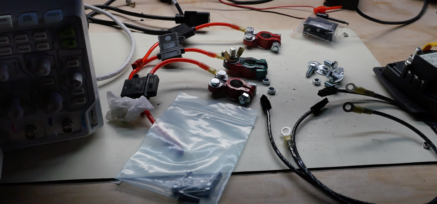
Each battery box has one battery, a set of cables and a 20A fuse box.
Cables are crimped with Anderson Powerpole connectors.
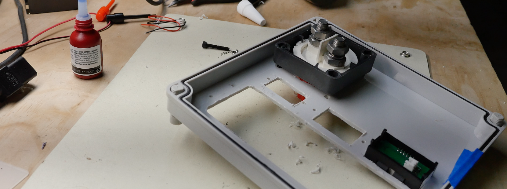
Cut Power Distribution Box
It is hard to cut plastic. I used dremal to cut(melt) windows for fuse box, switch and power connector.
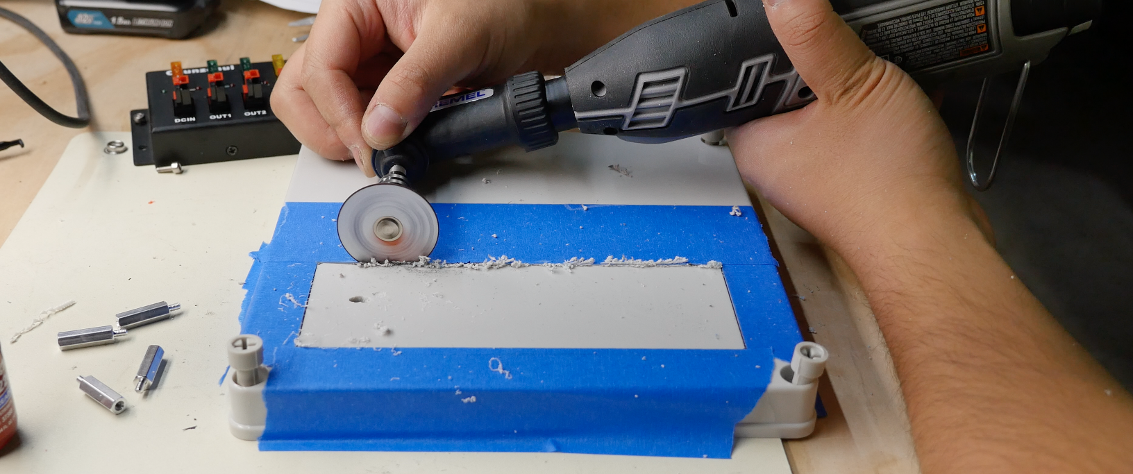
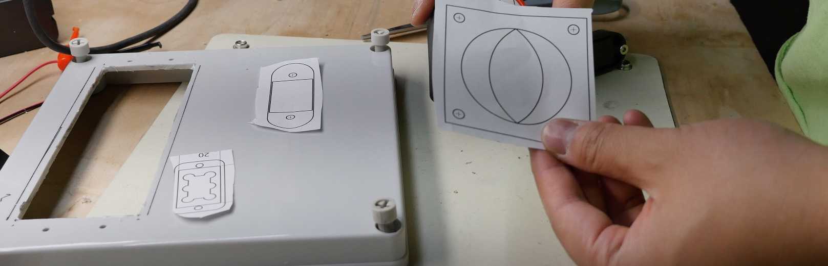
One trick I found very useful is modeling each parts in the Onshape.com and print out the 1:1 scale drawing. By cutting off each part and align them on the box, it is easy to find the correct position and cut line.
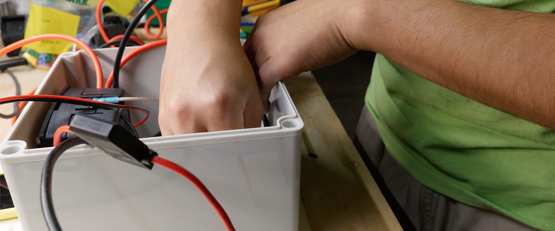
Wiring
Wiring is non-trivial task. Any mistake can result in a blow up junk. I followed schematic and did continuity
test on each point. After checked for three times I connected the battery with heart in my throat.
Luckily nothing bad happened and everything worked like a charm.
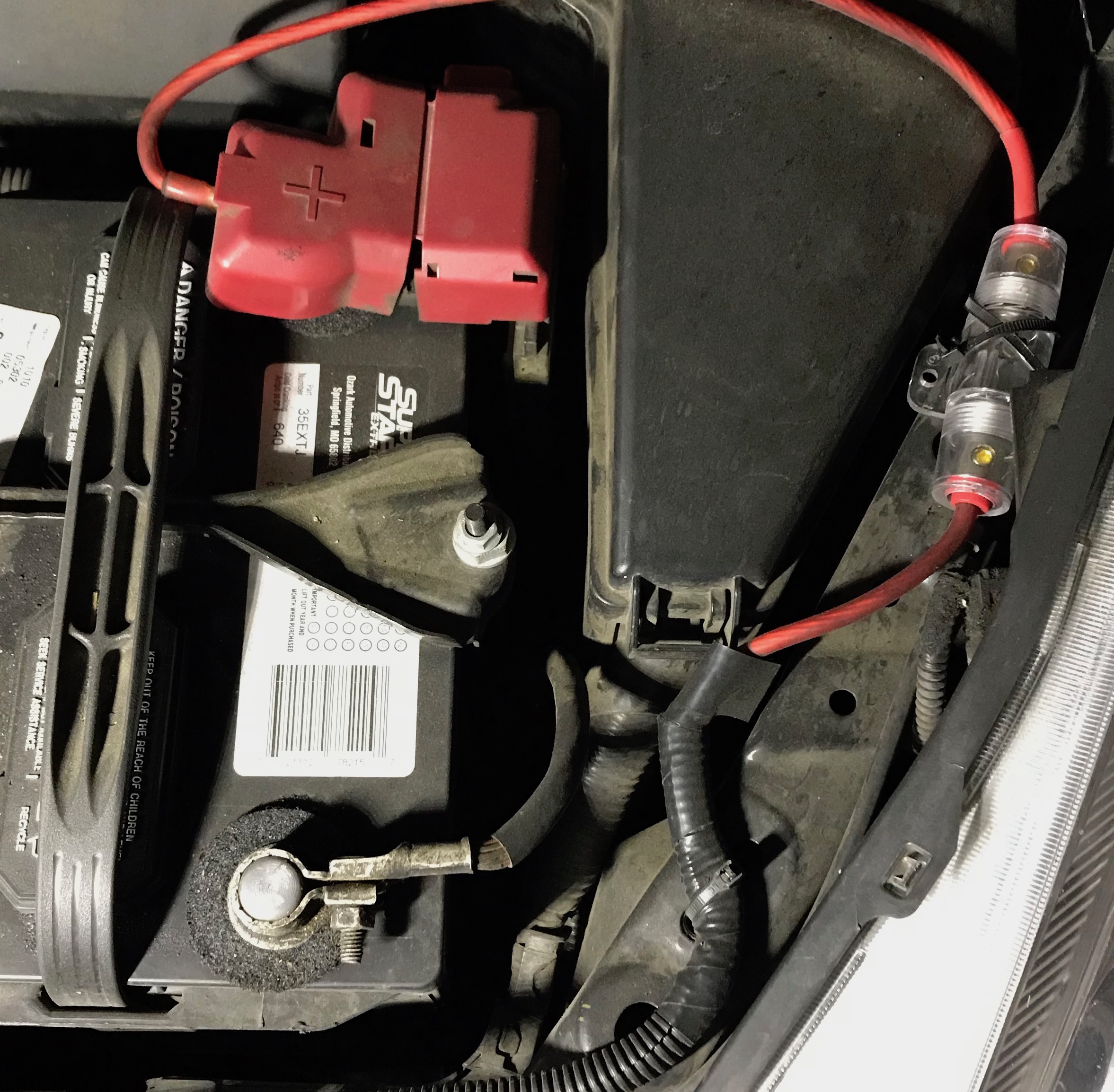
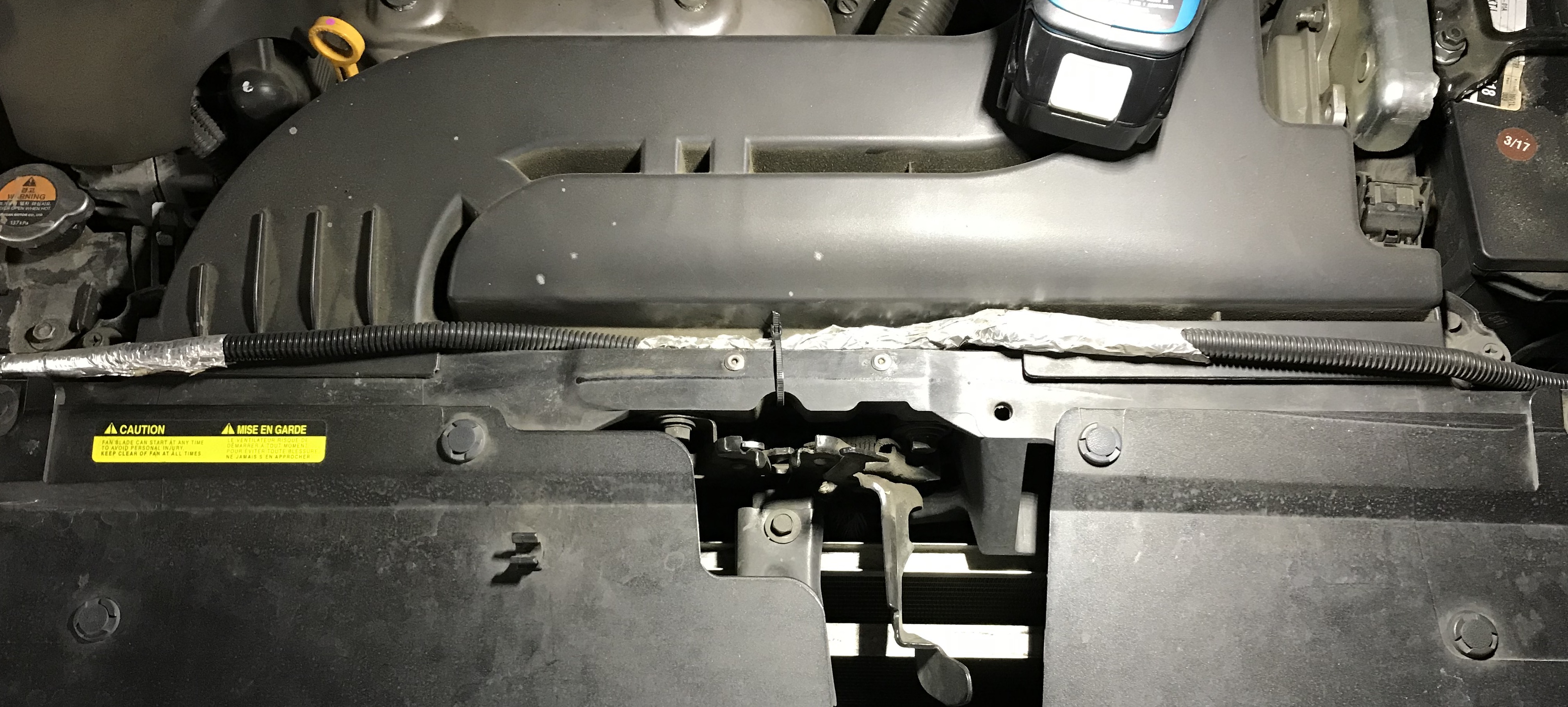
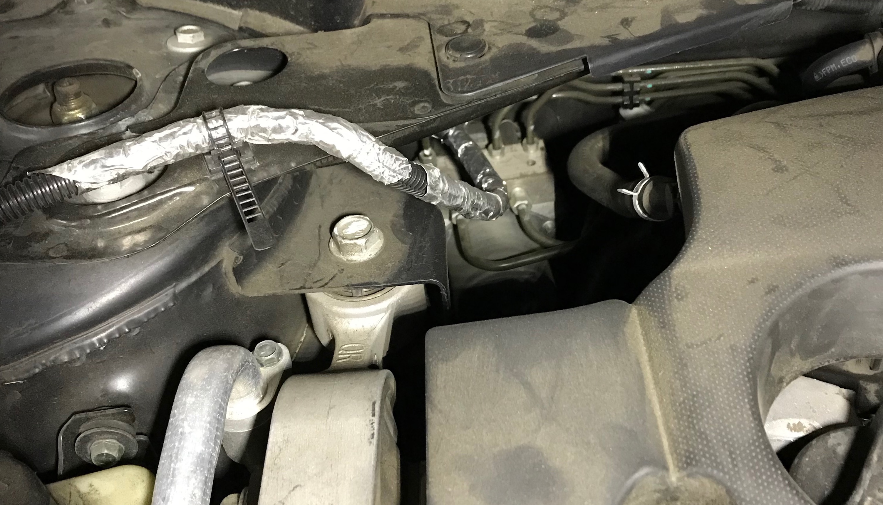
Following two images were coming from PowerBox1 project in which I did the vehicle harness wiring.
I wired from vehicle battery through the grommet under the gloves box and continue under two doors and finally
connect to the Power Distribution Box in the rear seat. By the way, I removed back seats.
Test
The whole PowerBox2 battery system can power on the computer deck for around three days. However I found that
driving my car in normal daily basis cannot charge the PowerBox2 system to surplus the power consumption, which means
the onboard system will run out of battery some time.
This problem can be solved by shutting down part of the onboard system while I am not driving the car, but this
solution depends on the low power onboard system and better power management PCB which is in the next milestone.
Simply replacing the charging cable with thicker one may solve the problem in short time but not in the long term,
because there will be more onboard devices that need more power.
As for now, I choose to shutdown the onboard system when I am not using the car.
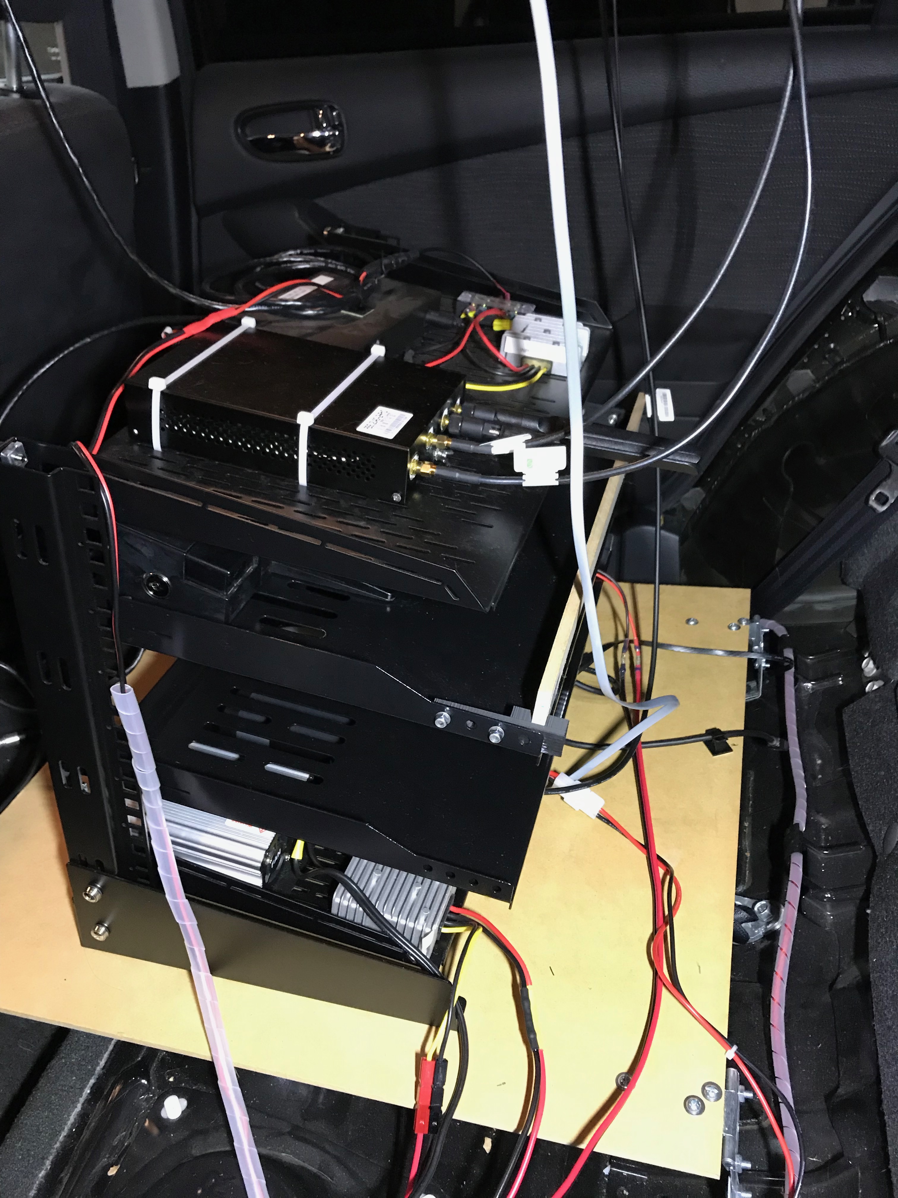

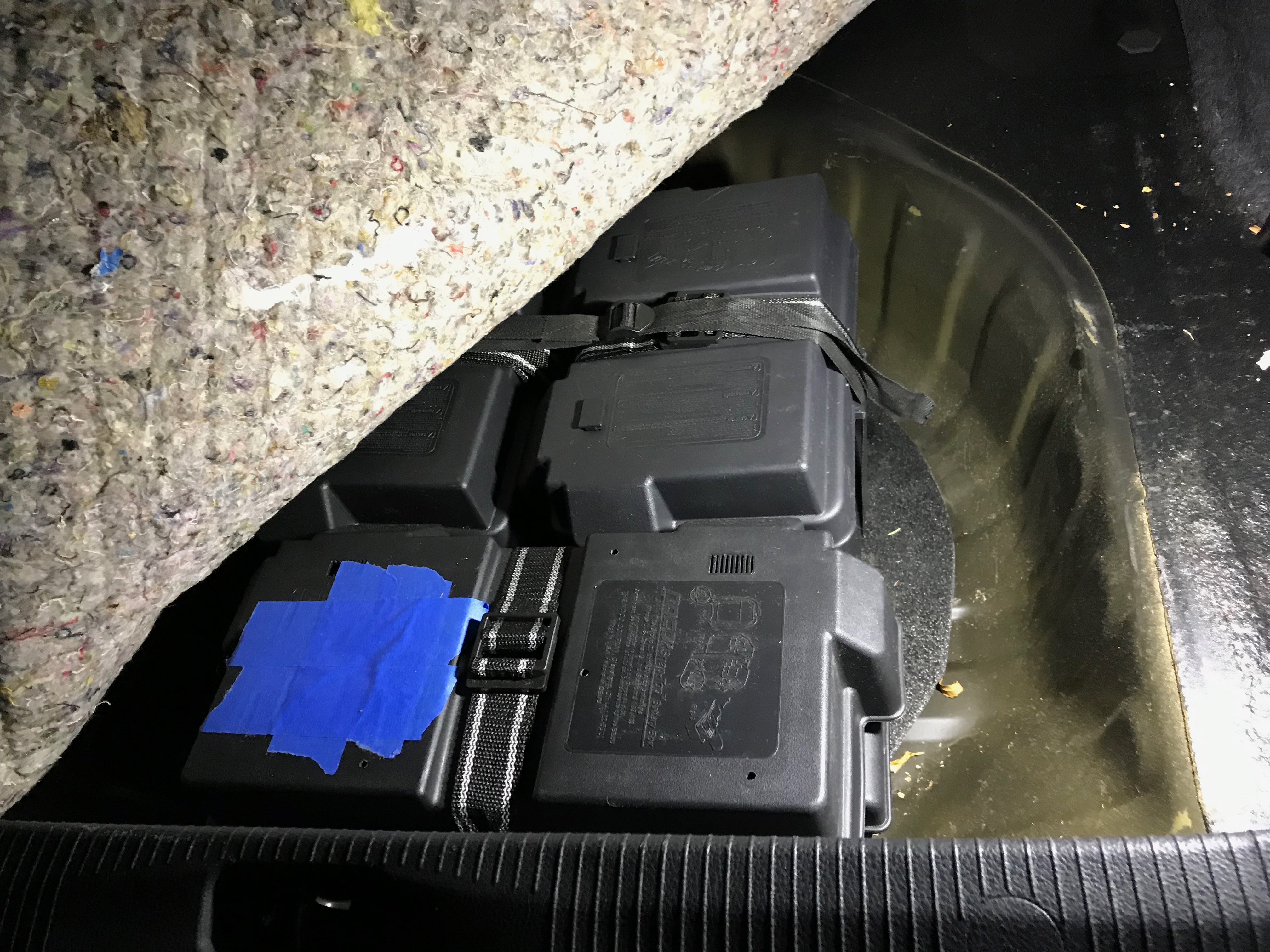
Hide batteries in the car
I have to sacrifice my backup tire to hide the big three battery boxes.