Post overview
- Intel Edison
- Design Criterias
- Schematic Design
- Test
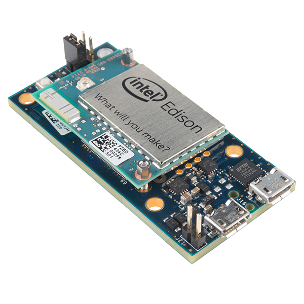
Intel Edison
Intel Edison is one of the most popular single-board computer in the market, which includes Raspberry Pi, Beaglegone Black, Odroid and so on.
Intel Edison has on-average hardware specs:
- Dual-core Intel Atom core @ 500MHz
- Intel Quark MCU @ 100MHz
- 1GB dual-channel LPDDR3 RAM
- 4GB eMMC
- On-baord WIFI
- On-board Bluetooth
But what is the most important feature for us, is that Intel edison is built in very compact size:
Desgin criterias
Baseline functionality
In our design, as companion computer, Intel Edison must be able to setup mavlink to pixhawk over Serial port, so the baseline functionality is power regulation circuit and UART connection circuit.
Here is the problem. By default, the intel edison has 1.8V logic level on most of its pinouts, including GPIO, UART, SPI, I2C, PWM, and analogs. So we need to level shift all the ports that we need.
Extra features
Seperate battery provides smoother voltage and stable power supply, so it would be nice to monitor the battery voltage and current consumption. In our application, we use a MCP3426 external ADC chip and an ACS711 Hall-effect sensor to measure the current.
Plus, Intel edison also need to talk to the other onboard devices, so it should have pinouts for PWM, I2C, SPI and GPIOs. Ofcourse, all of those ports should be protected by level shifters.
Also, keeping clock running is important for compiling, so we need a backup coin battery powering on the Intel edison’s internal clock.
Schematic Design
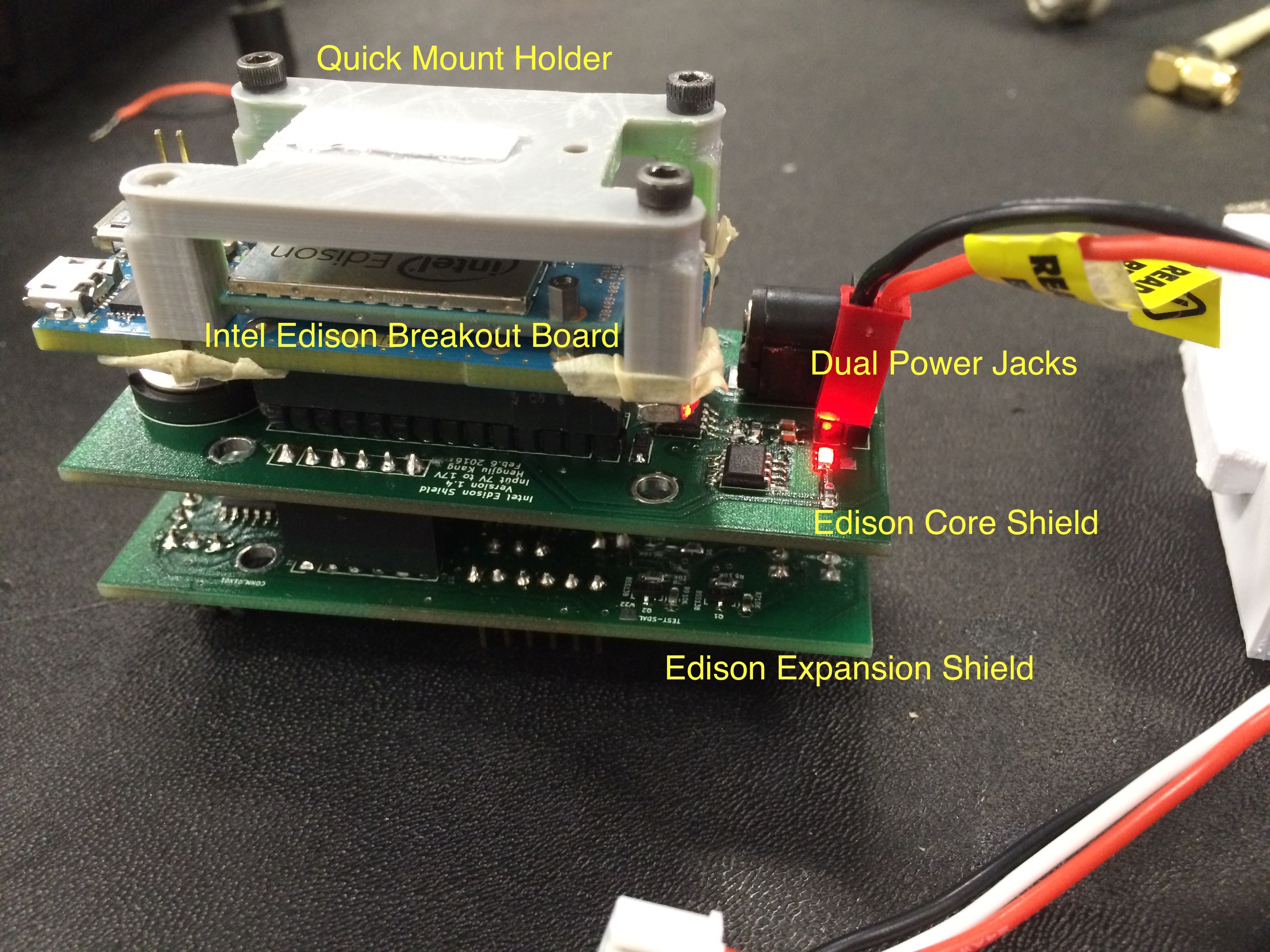
In order to lower the design risk and making the mother board smaller, I modularized the mother board into two parts:
- Core Shield
- Expansion Shield
Core Shield
This is the core shield that supports the Intel Edison for the baseline work: Controlling the Pixhawk.
So we have the following parts/circuits on the Core Shield:
- Dual power jacks
- ACS711 Current sensor
- MCP3426 ADC
- 1.8V to 3.3V level shifter for I2C
- TXB0104 1.8V to 3.3V level shifter for UART
- Breakout pins to expansion shield
- RTC Backup battery
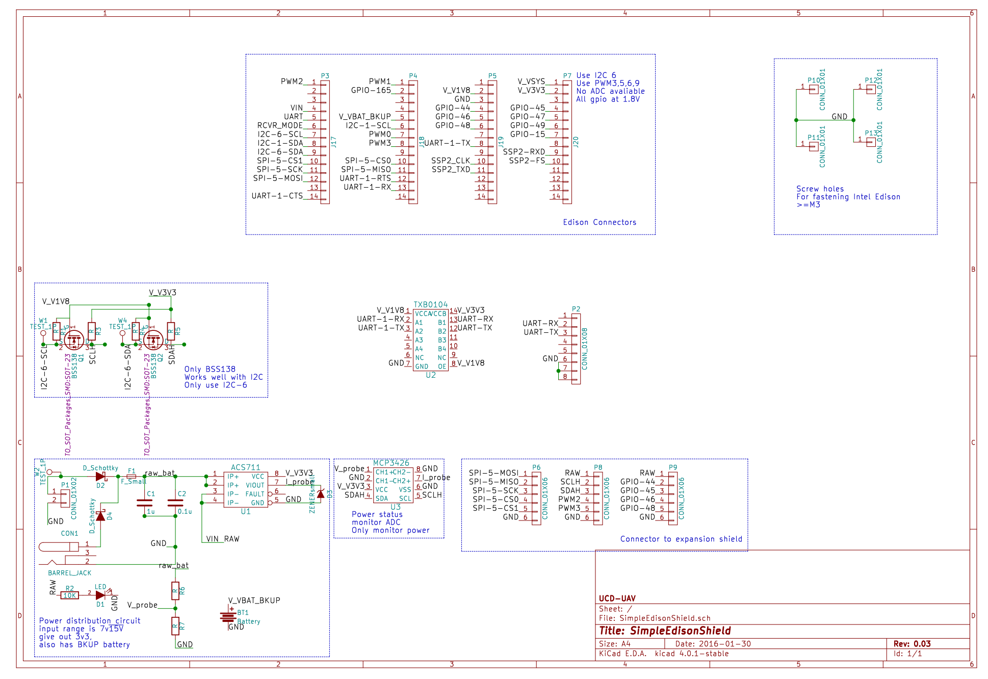
Remind: Serial port, I2C and SPI protocols are implemented in different ways, so they have different parameters. For example, UART is usually high impedance, and SPI is open drain. So in our case, we use MOSFET to build a level shifter for I2C and use TXB0104 chip for UART.
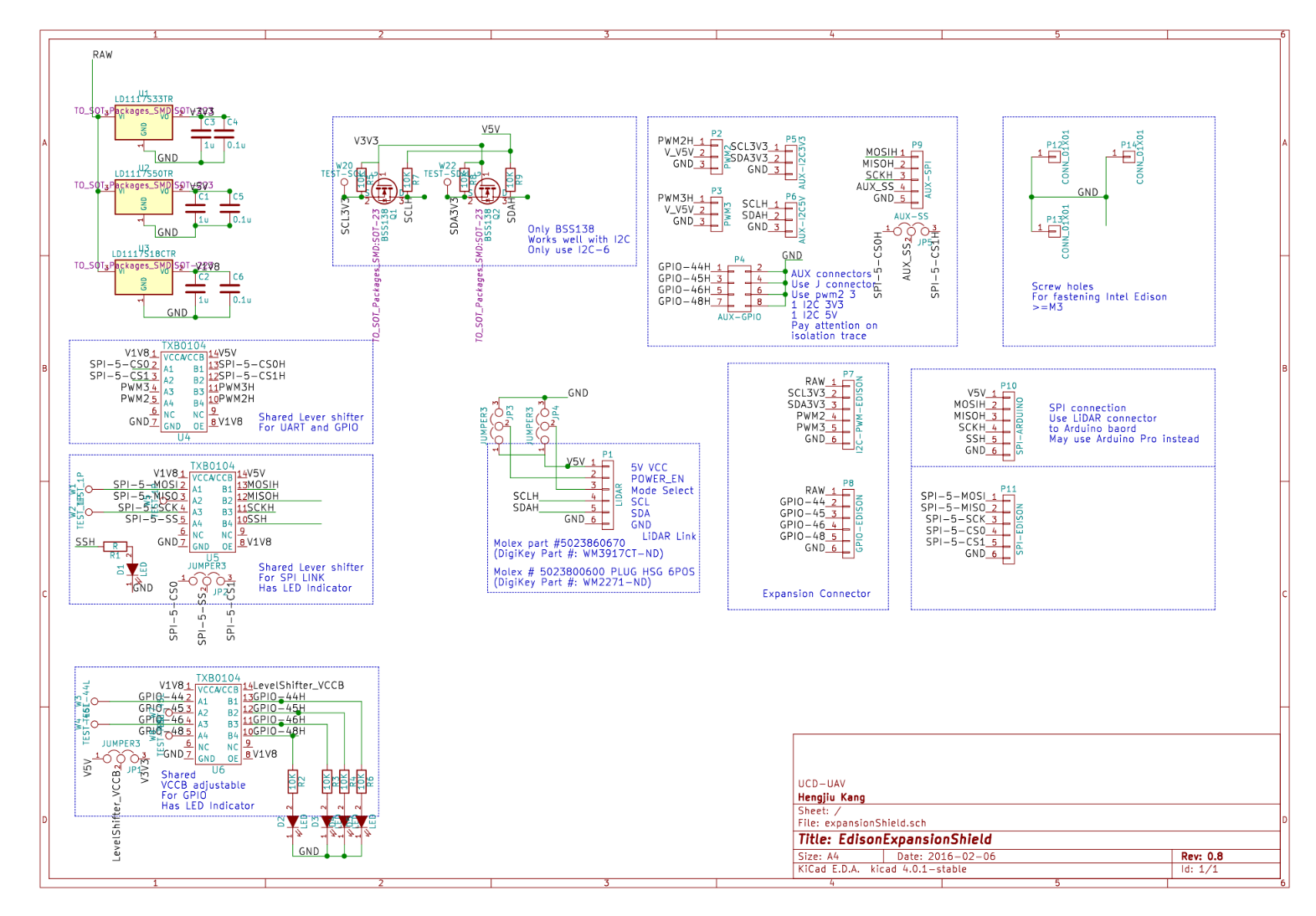
Expansion Shield
Expansion Shield is nontrivial design. I layout more regulators, more pins and more selectable level shifters. Here is the schematic of Expansion shield:
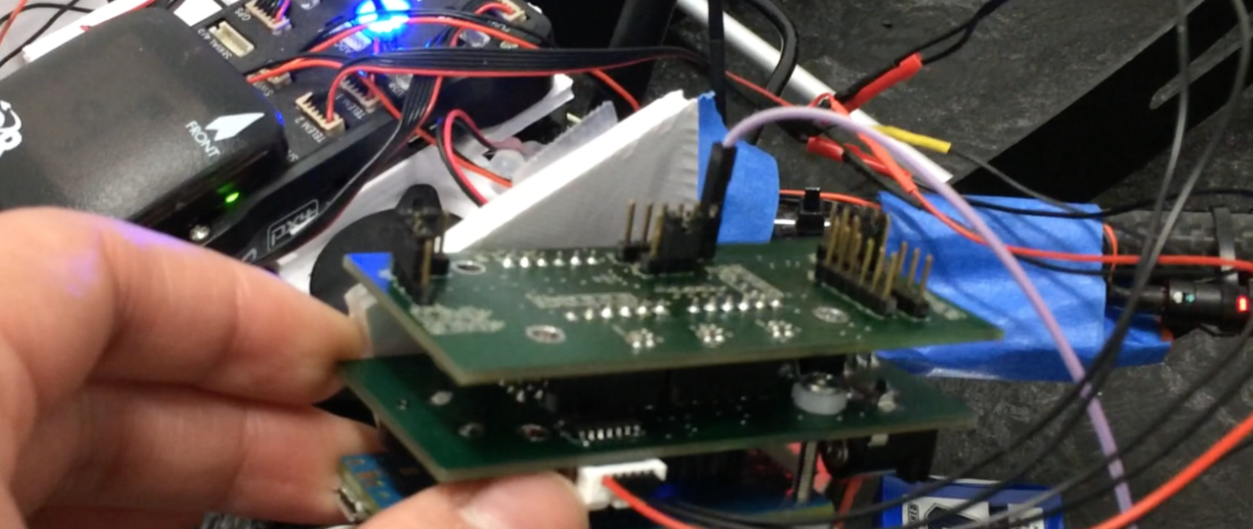
Test
 After assembling, the high speed Serial port (921600bps )between pixhawk and Intel Edison worked like charm, but Edison could not connect to the current sensor and external ADC. I used oscilloscope and found that the waveform was correct, so there should be other problems.
SPI port on expansion board was also working, and we used it to connect to an external Arduino to collect data from remote data logger via XBee.