Post overview
- FreeRTOS, STMCube and HAL
- STMCube Setup
- Real code
- Blink!
FreeRTOS, STMCube and HAL
FreeRTOS is an open source RTOS which has been ported to many platforms including ARM, STM32, and etc. They reason why we use FreeRTOS is that, when application becomes complex and each part has relation to each other, writing in bare MCU will be pain. And the FreeRTOS middleware makes it easier to port the software design to another platform.
STMCube is a tool to configure the hardware resource of the STMx0 to STMx4 controller, and it can generate all the initializationg code for the users. Then I dont need to struggle in the initialization for hours and hours and read the hundres pages of datasheet and user manual for every chip.
Also, the HAL driver is a common-use driver library developed by ST. It offers a complete suit of interfaces and APIs and functions to make each IP easy to use. It is even in a higher level of well-known library CMSIS.
STMCube Setup
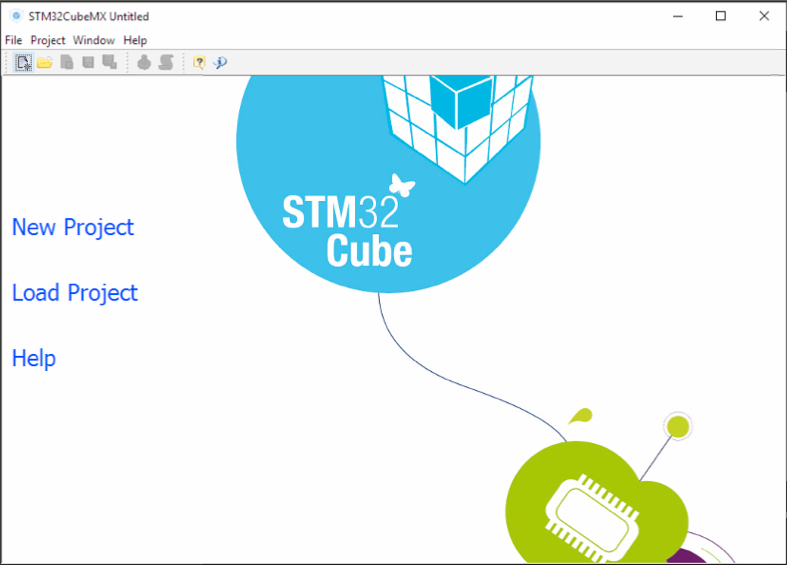
In the startup window of STM32CubeMX, we choose “New Project” to make sure that the workspace environment is clear.
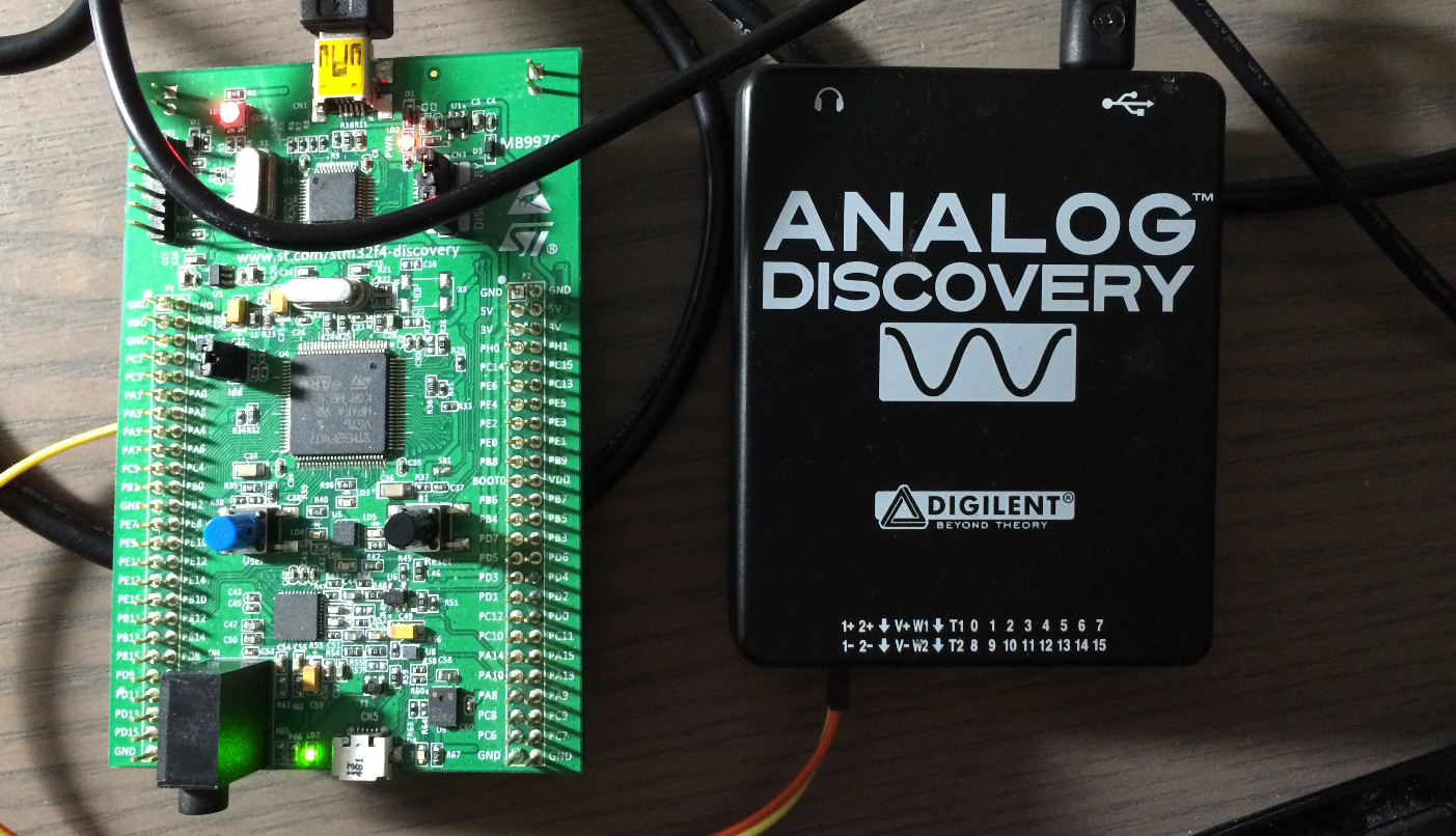
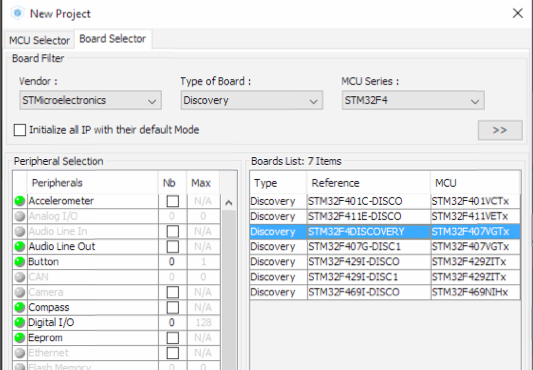
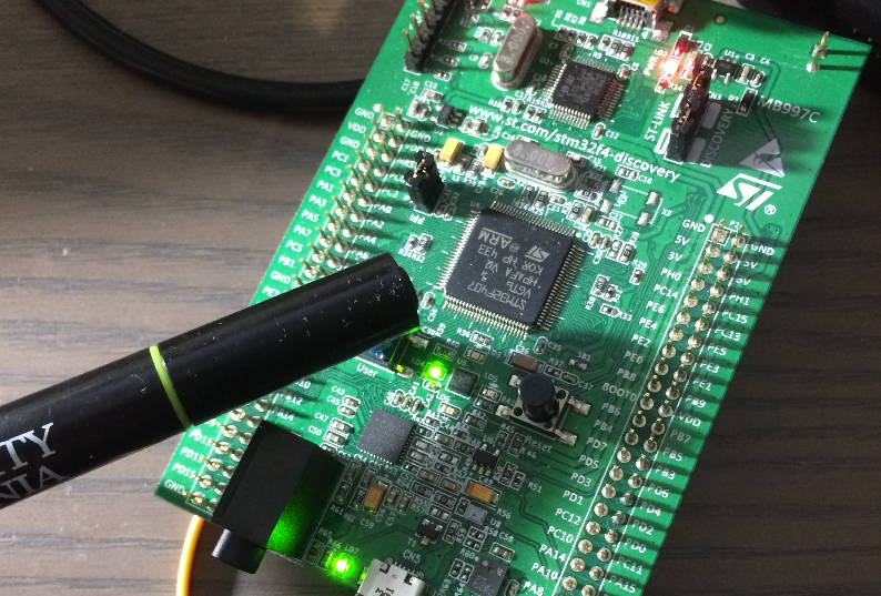
Then choose our baord: STM32F4-Discovery board, based on STM32F407VGT6 chip
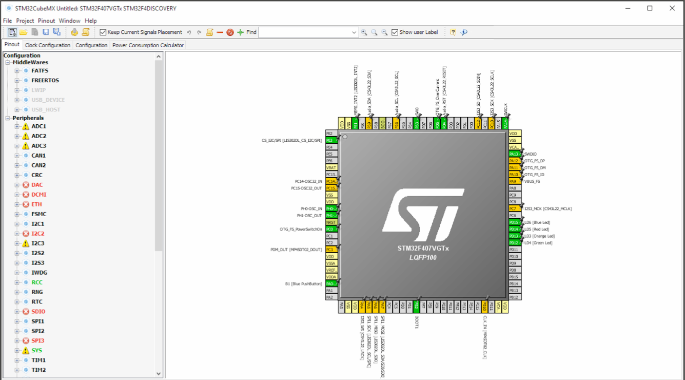
This is pin definition graph. It may differ by board, and if you were choosing by chip but not board, you may not have this many configured pins. Dont worry, we only need PA0, the button, and PD12, the green LED on the board.
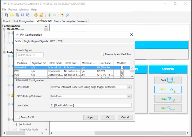
In the “Pin configuration” under the “Configuration” tab, we change the PA0 GPIO mode to External Interrupt Mode with Rising edge Trigger Detection and enable Pull-down resistor.
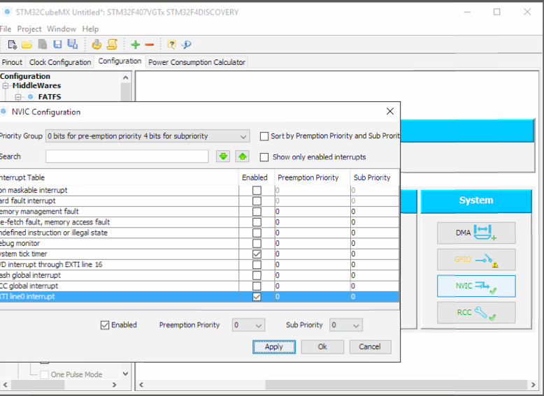
Then we need to enable the NVIC, or the interrupt service. In the NVIC tab, we enable the “EXTI0 line9 interrupt”.
Tip: At least in STM32F4 board, every GPIO pin can be set as External Interrupt mode. But there are only 15 EXTI lines, and Px0 will trigger the EXTI0 line, Px1 will trigger the EXTI1 line, and Px 12 will trigger EXTI15_9 line. To be more specific, PA0, PB0, PC0, PD0 will all trigger the same EXTI0 line.
Then we can generate the code. We use Keil V5 (MDK-ARM V5) in this post.
At this point, we need to know several things:
- All the initialization code has been generated and been setup, thus we dont need to write our own.
- STMCube uses FreeMarker template Engine to generate codes and protect the user code, so dont write code outside the prompt like “/* USER CODE BEGIN 1/” and “/ USER CODE END 1*/”
- We do the binkly in two ways, the one is just using interrupt, and another one is blink the LED by semaphore.
- In the easier method, we just call “HAL_GPIO_TogglePin()” in the Interrupt handler function.
- In the RTOS style method, we set the falg in Interrupt Handler function and process the blink in a task.
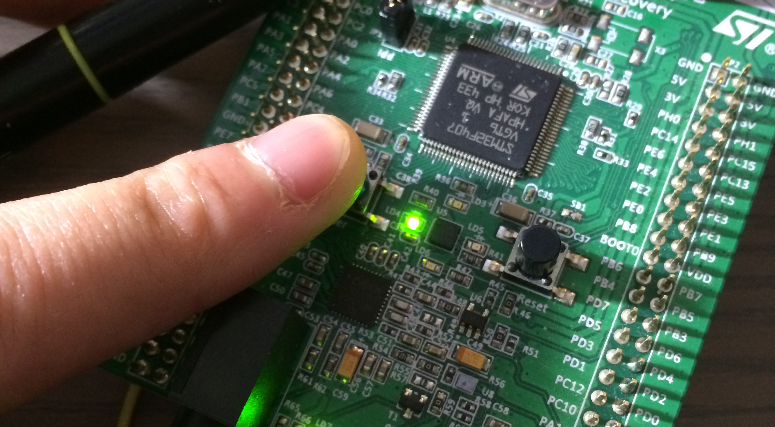
- The green LED in this STM32F4-Discorvery board is PD12.
Blink! in Traditional way
As far as we know that simply calling “HAL_GPIO_TogglePin()” in Interrupt handler function is enough, we just go in this way first.
We can overwritten the Interrupt Handler funciton in user code file, but I just write it in the generated file called “stm32f4xx_it.c”
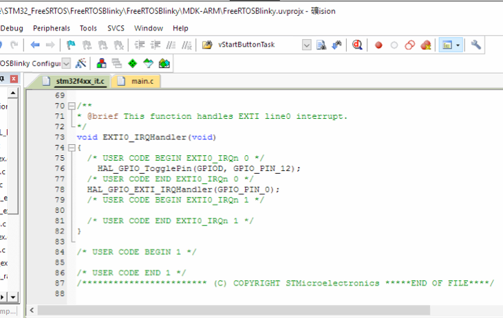
Tip: We dont need to manually clear the interrupt flag in the interrupt handler, because the handler we saw here is not the “raw Handler” but the one has been processed by HAL driver. On the other words, HAL did the clear interruptpending falg for us.
Blink! in FreeRTOS style way
Because we are using FreeRTOS for the purpose, it will be natural to let FreeRTOS do the interrupt handling job for us. To be more specific, let the FreeRTOS scheduler handle the event.
The “Semaphore” is the flag that we need. First we create a Semaphore in Main.c (not neccessary) and create a blink handler task, then we set the semaphore in the interrupt. Once semaphore set, the task will read that and do the codes we defiend.
In the main.c file, we do the following things:
-
Create semaphore and prototype of task
/* USER CODE BEGIN 0 */ SemaphoreHandle_t xLEDSemaphore = NULL; void vLEDBTNTask(void *pvParameters ); /* USER CODE END 0 */ -
Configure the semaphore and creat task in main loop after all the initialization
/* USER CODE BEGIN 2 */ vSemaphoreCreateBinary(xLEDSemaphore); xTaskCreate( vLEDBTNTask, "BTNx", configMINIMAL_STACK_SIZE, NULL, 0, ( TaskHandle_t * ) NULL); /* USER CODE END 2 */ -
Implement the task
  void vLEDBTNTask(void *pvParameters ){
  configASSERT( xLEDSemaphore );

  /* This is the task used as an example of how to synchronise a task with
  an interrupt.  Each time the button interrupt gives the semaphore, this task
  will unblock, increment its execution counter, then return to block
  again. */

  /* Take the semaphore before started to ensure it is in the correct
  state. */
  xSemaphoreTake( xLEDSemaphore, 0 );

  for( ;; )
  {
      xSemaphoreTake( xLEDSemaphore, portMAX_DELAY );
      HAL_GPIO_TogglePin(GPIOD, GPIO_PIN_12);
  }
  }
Move on to the stm32f4xx_it.c file, we do the following thins:
-
Add some include and externs in stm32f4xx_it.c:
/* USER CODE BEGIN 0 */ #include "semphr.h" extern SemaphoreHandle_t xLEDSemaphre; /* USER CODE END 0 */ -
We modify the interrupt hanlder function:
  void EXTI0_IRQHandler(void)
  {
      /* USER CODE BEGIN EXTI0_IRQn 0 */
      BaseType_t lHigherPriorityTaskWoken = pdFALSE;
      xSemaphoreGiveFromISR(xLEDSemaphore, &lHigherPriorityTaskWoken);
      /* USER CODE END EXTI0_IRQn 0 */
      HAL_GPIO_EXTI_IRQHandler(GPIO_PIN_0);
      /* USER CODE BEGIN EXTI0_IRQn 1 */
      /* USER CODE END EXTI0_IRQn 1 */
  }
Here is what we have!