Post overview
- TinyCar Solidworks sketch
- TinyCar Sensor bar
- TinyCar Propulsion
- TinyCar IMU
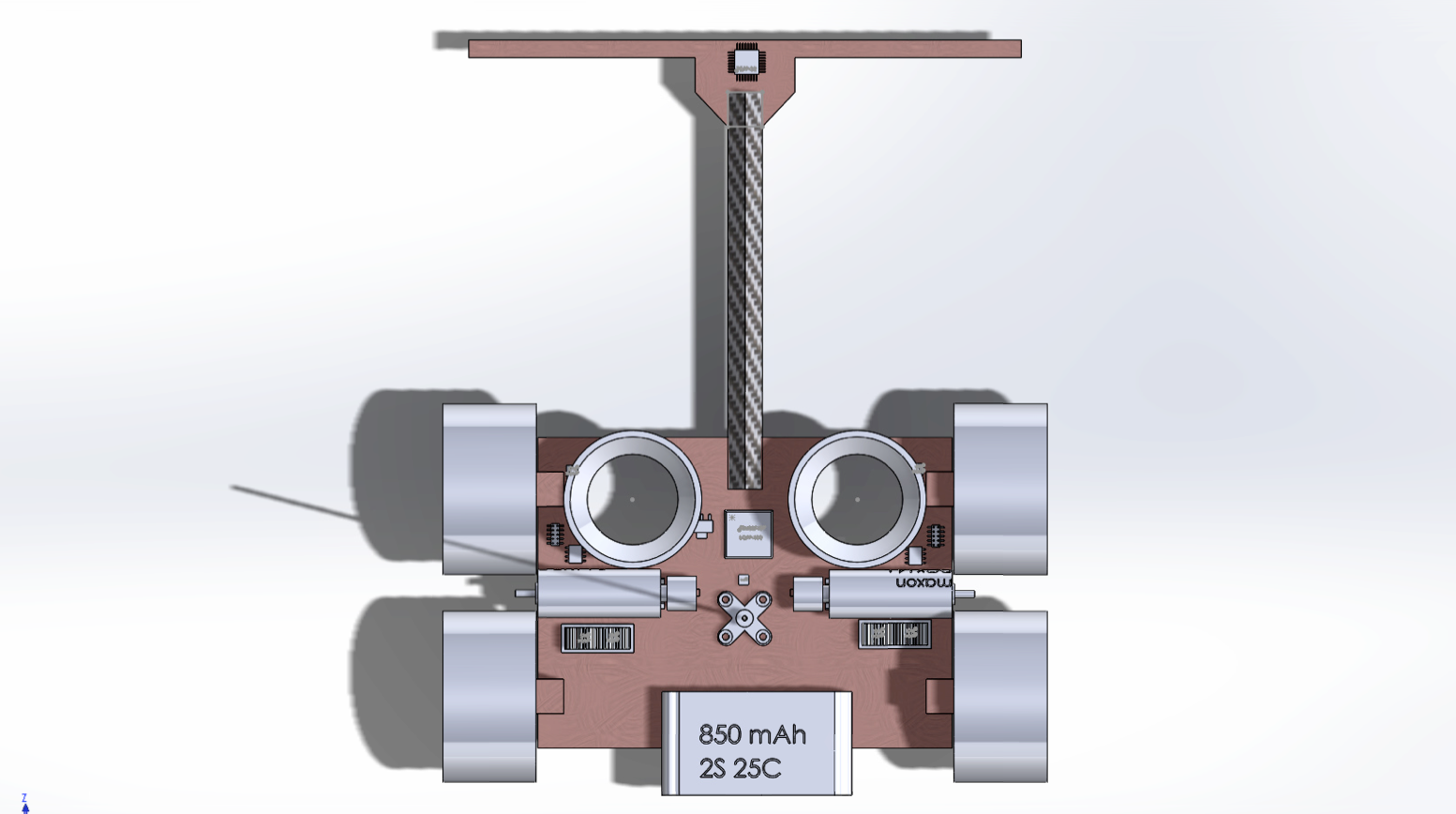
TinyCar0 Solidworks sketch
Because we dont have enough knowledge of chassis design, so we only came up with dimension values and put things together first, make the car rolling. This is Type0. After that, we can start on building Type 1, which maybe the “release” verion of TinyCar.
The sketch above shows the following parts:
- Battery
- Motors
- Downforce fans
- Motor drivers
- Pole stand
- STM32F4 controller
- Sensor bar
The competition last at most 5 mins, so we chose a 850mAh 2s1p battery pack, which can hold the energy for 5 mins at 10.2A current. Quite enough. The battery should be put as rear side as possible, because the center of mass issue. TinyCar uses differential steering, so the distance between two wheels on each side is short, making it hard to keep balance, so the battery is a kind of weight as another role.
In order to keep the approximate power-to-weight ratio of CurtisX04 car, we choose more powerful 14mm diameter motors from MAXON. This motor can output at maximum 10 Watt power and eat ~1.5A current each.
TinyCar Sensor bar
Another team member J.G.Tao is working on Sensors. Basically, we use infarad diode to detect the trace. Most infarad sensors will be on the sensor bar infront of the car, and in order to minimize the impact of ADC reading delay to the main algorithm thread, and also for seperating the jobs for members, we also put an ATMEGA328P chip on the sensor bar to read the value, calculate the position of the trace, and send back to the STM32F4 MCU by either I2C or SPI.
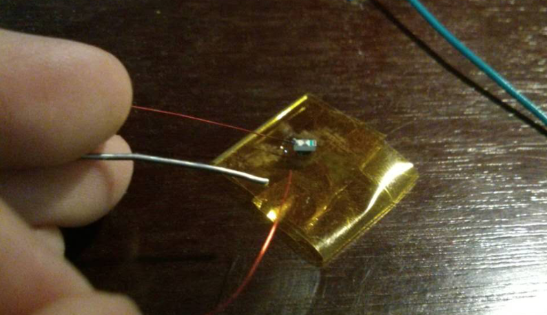
They are VSMB10940 and VSMB10940F pair, with good angle of view and good response delay.
Each pair can cover 1cm wide range on the ground, and trace is 1 inch, so we plan to put 8 pairs underneath of the bar.
According to the test, this pair is good.
*Design details will be posted on another post.
TinyCar Propulsion
Finally we picked up DCX 14L motor from MAXON. This is a compact size, high power (10W) DC motor that can fit out car. The motors will be located on the middle of the car, and drive two wheels at the same time.
The most important thing is motor driver. According to the rule, we need to design our own motor driver. The motor driver should have compact size and enough current rating, also it should be able to brake the motor. At the beginning, I chose MC33883 and common TO-220 packaged n-Channel MOSFET as driver design, but when I drew the Type0 sketch, I found problems: They occupy too much area. MC33883 is Through hole chip, though we can cut the foot and make it surface mount, the package is still too big. Also the MOSFET either has exceed current rating and TO-220 is large.
Finally by searching for TI and Linear for long time, I chose the following combination:
- MOSFET: CSD17308Q3
- H-bridge IC: LM25101
Each motor needs two MOSFET and one H-Bridge IC, and two MOSFETs will be put under a heatsink, immursed in Thermal Compound. MOSFET will drain the current directly from the main power line, and control signal will be given from H-Bridge IC.
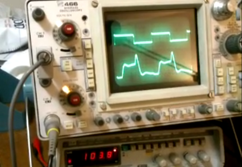
*Tip: It is totally possible for MCU directly handling the MOSFET, but since the Gate of MOSFET had capacitance, when PWM frequency added on the gate is high, and MCU cannot drain enough current on contorl pin, the MOSFET may not turn on and turn off as expected. We would say the MCU cannot drive MOSFET well. So the H-bridge IC, or the MOSFET Driver IC, are used to isolate and drive the MOSFET.
TinyCar IMU
IMU is short of “Inertial Measurement Unit”, and often used in Inertial Navigation system. Our TinyCar needs IMU to simulate/draw the trace map in the first run, and guide the car runing in an optimized route in the second and further run. We are not only optimize the route in the second run, but will also fully guide the car in some complex trace like “step function part”, which require a very precise IMU. Also, the TinyCar has lot of vibration both containing the low frequency part, from the chassis, and high frequency part, from dynamic motors and downforce motors. However, we only need inertial navigation keep its precision in short time/short range, because the course is short, and we have powerful CPU to do the complex algorithm, like Kalman filter, which can do our a little bit favor.
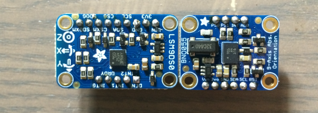 There are many 9-axis IMU chip on the market, but I bought two of them to evaluate.
- LSM9DS0
- BNO055
Both of them are from Adafruit, but LSM9DS0 has very high refresh rate and higher precision, and BNO055, from BOSCH, amazingly has Cortex-M0 inside and can do the Inertial navigation calculation and output the euler coordinate, which can save a lot of CPU time.
Test/Comparison will be posted on another post.