Post overview
- We need ankle band, which we named snake-band
- We started from circuit board
- Then we design case for it
- Beta product
We need ankle band, which we named snake-band
There are two things that we need to make sure that our NaughtyBall can locate itself correctly. One is IR Cameras, and another one is IR LEDs, which is a wearable band for user, so we need to design an ankle band for user.
Driving LED is not very straight forward, because turning a LED always on will generate a lot of heat, so it is a good idea, or even necessary to design a flashing circuit. Another problem is that, we need a ring of LEDs, but turning over ten high-power LEDs will consume much power. As long as we only want to use a small size battery, it is hard for a band work for several hours. If you have ever used tactical flashlight, you should have sense of its battery hunger.
So we have two basic design guideline:
- Each node should be lighten up by some frequency
- A complete ankle band is stacked with several nodes, but we want to turn each node on one by one or in pairs.
We started from circuit board
TI TINA Simulating
We started with a node.
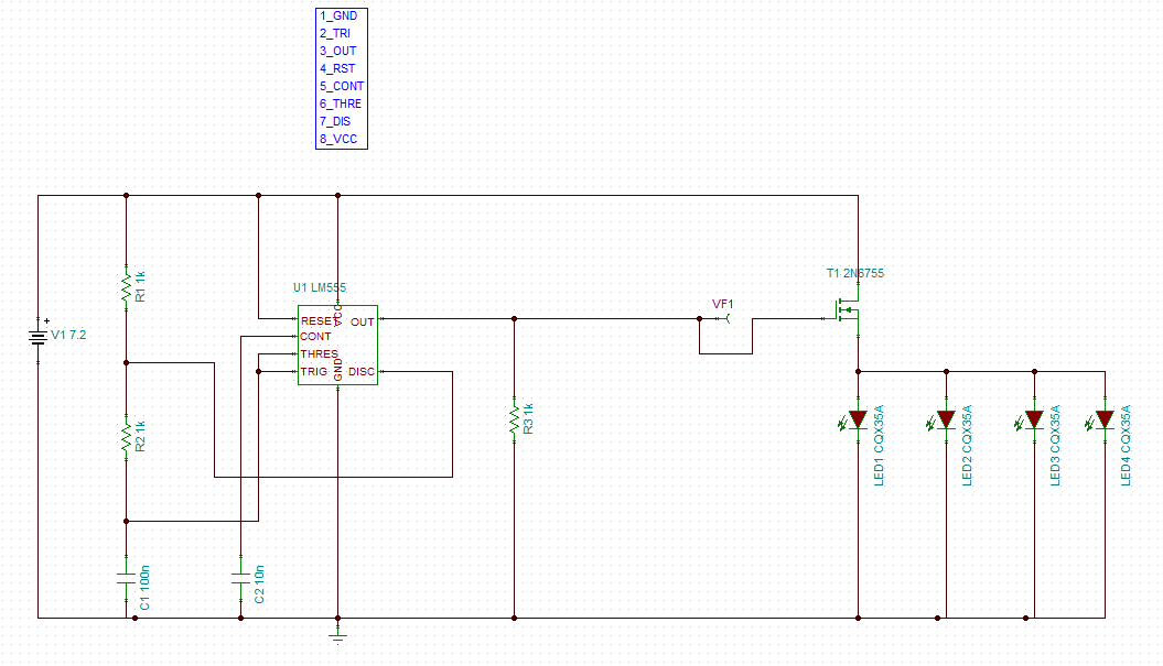 Early time simulation circuit on TI TINA
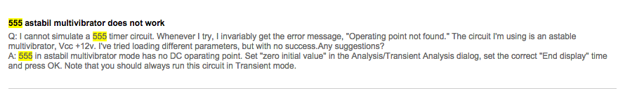
I spend a daytime on using TI TINA to simulate a 555 flashing circuit with four LEDs, finding a circuit for one node. Unexpectedly, I cannot get correct voltage and current results. I checked out my 555 output buffer, MOSFET design, but I still did not know what was wrong. Finally after googling, I found that unstable device like TLC555 can not be simply simulated using SPICEfrom link 555_err_source
Also I realized that system will be overengineered if I design such a timing circuit in each node, so I decided to move on simpler version of node.
UPDATE: However, at the time I am writing this post, I understand that we can simulate 555 if we carefully design it in ASYNC mode following reference design.
The source link is: 555 timer model error?
Design circuit board
- Version 0.1
We have many 4-pins wires, so I can make it tricky by designing a simple ‘mux’ on 4-pin. Lets consider four pins as VCC-S1-S0-GND, and S1, S0 has four combinations, then we can have four lighting rule choices for each node. We can use jumper to choice one mode for each node.
| S1 | S0 | Node0 | Node1 | Node2 | Node3 |
|---|---|---|---|---|---|
| 0 | 0 | True | |||
| 0 | 1 | True | |||
| 1 | 0 | True | |||
| 1 | 1 | True |
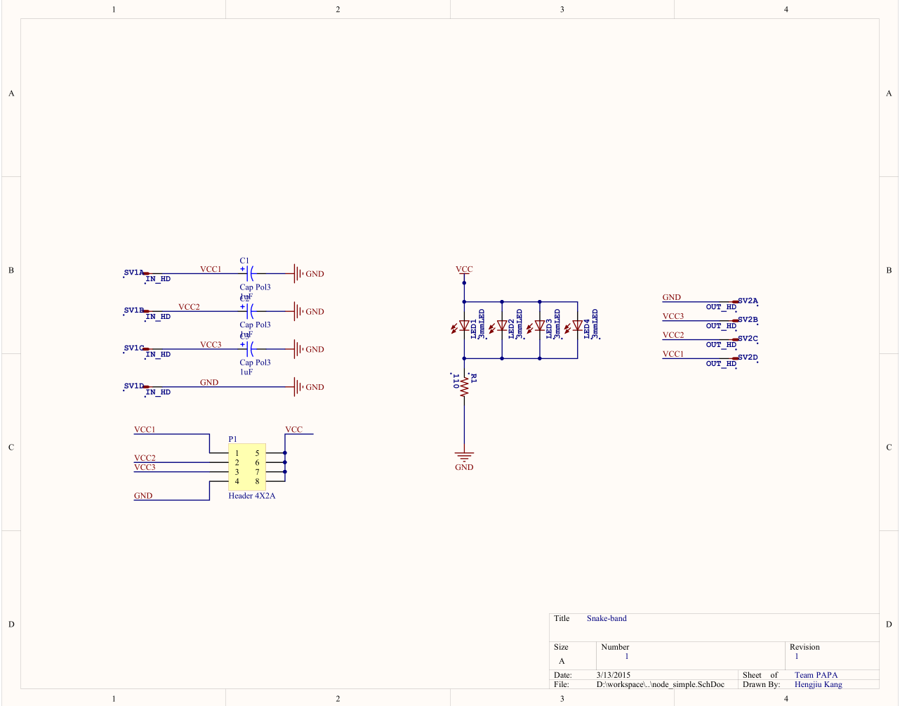
Our first version schematic is:
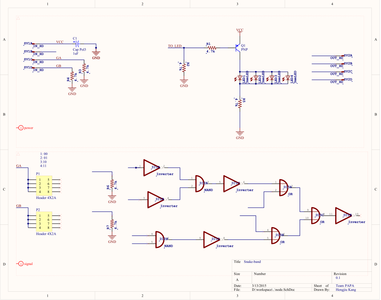
However, even before I finish schematic and put parts onto PCB design, I found that even using SSOP footprint chips is too large to fit in a 1 inch sqaure tiny board, which was so sad.
- Version 1
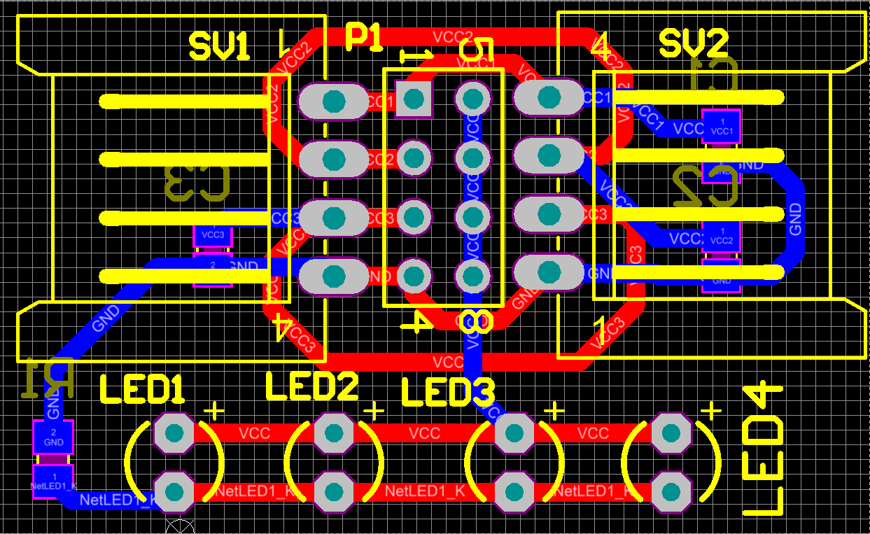
Simpler! Simpler! Simpler! Things may go out of control right now! Let’s sit down and solve problem straightly and quickly! Only want to make band works first, with some expand potential, rather than struggling in details, I came up with temporary final design. Still using 4-pins strategy, but 3 of them are power, and left one is ground. We will power on each node by simply turning on one of three power pins. That’s it.
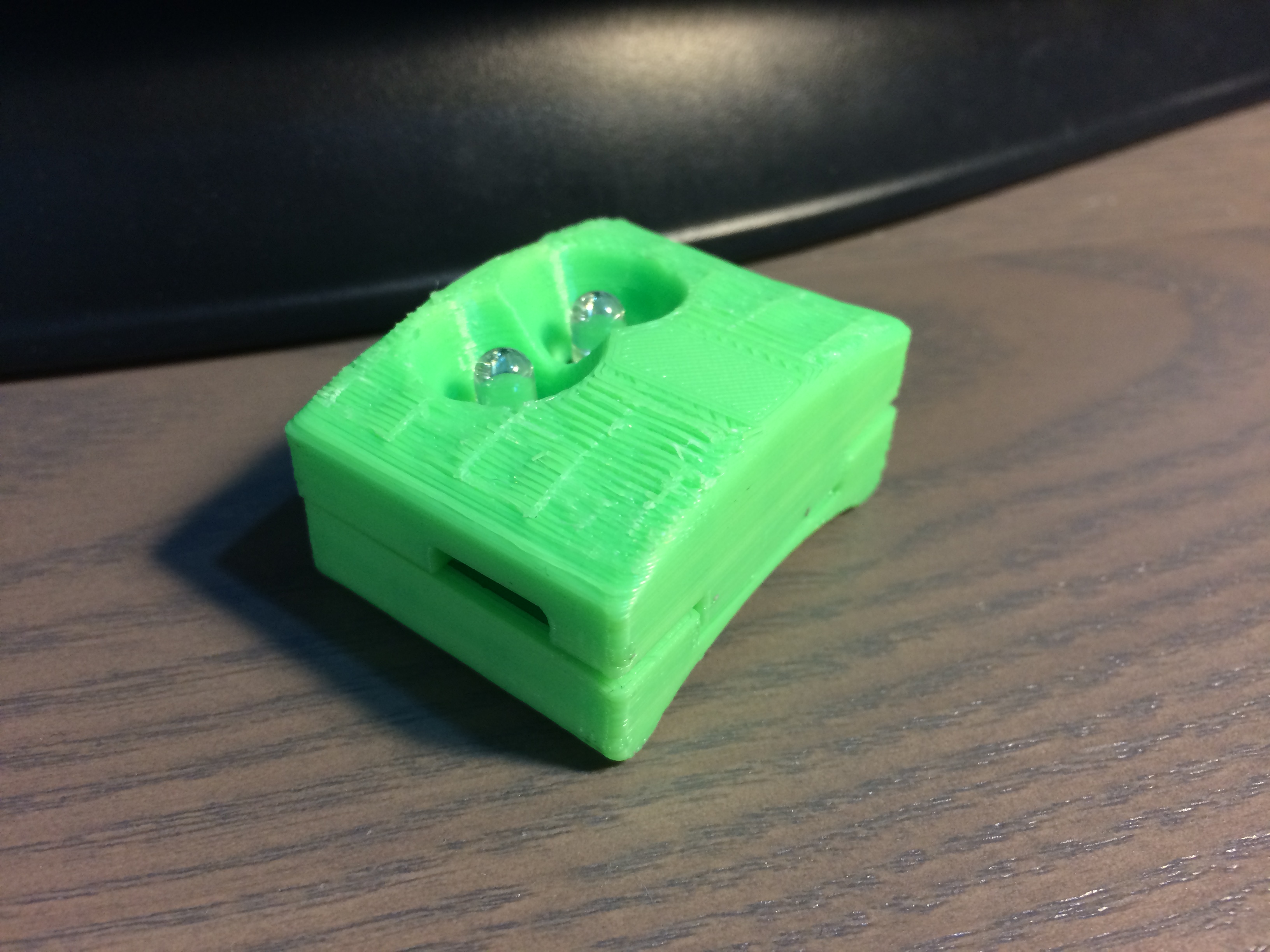
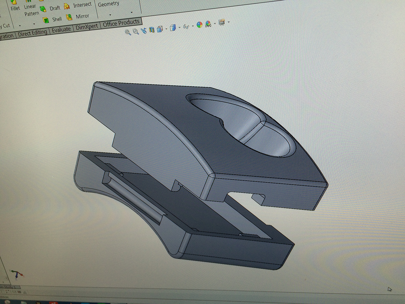
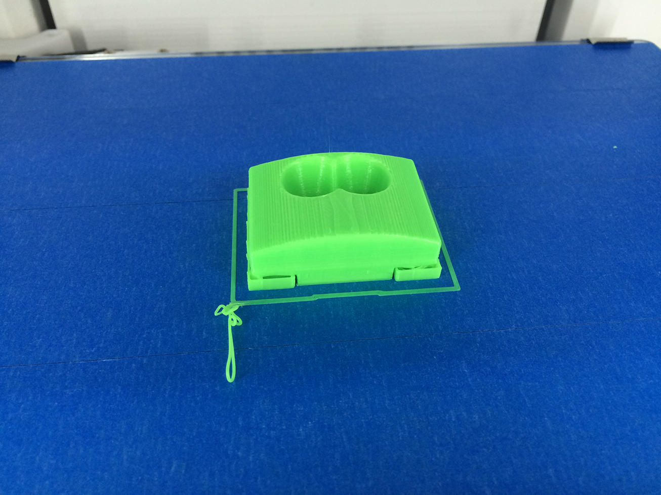
Then we design case for it
Things left became straight forward. Yunan designed cases for us. We wanna wear it, so each node should have curve to fit our ankle, and we plan to sew nodes and batteries on an elastic band, which will make it comfortable.
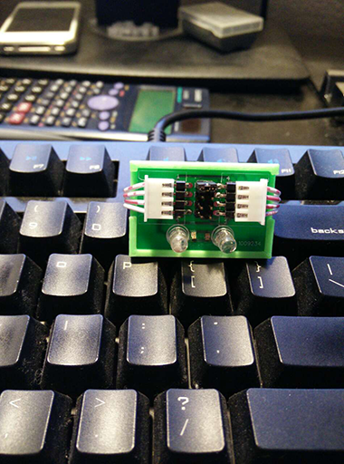
Beta product
License
Our Project: NaughtyBall has reached end of winter quarter 2015, but we will continually work on it until the day it become the one that we like.